Starting up
- 38 - 01.21909.2669.9-02
14 Starting up
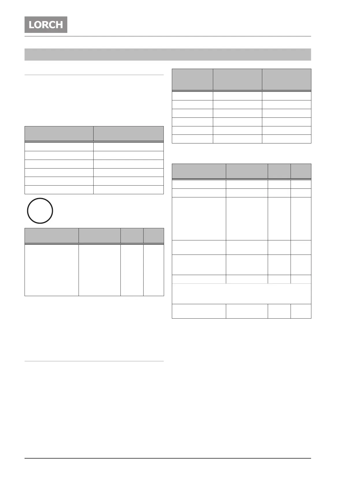
14.1 Electrode welding process
 Select the electrode welding process with button 30 (LED
electrode- DC 33 or LED electrode- AC 34 lights up).
9 You are in the parameter main current I1 (LED Main current
I1 37 lights up).
 Use the rotary knob 41 to set the desired current intensity.
9 Your welding machine is now ready for use.
Electrode diameter [mm]
Recommended current
intensity [A]
1,5 20 - 40
2,0 35 - 60
2,5 45 - 100
3,2 75 - 140
4,0 130 - 190
5,0 180 - 260
Heed the electrode manufacturer’s instruc-
tions.
Parameter Range
Factory
setting
LED
Main current I1
100 37
T 180 10 - 150 A
T 220 AC/DC 10 - 170 A
T 220 DC 10 - 180 A
T 250 10 - 200 A
T 300 10 - 200 A
Tab. 1: Main parameters
The factory setting values are optimised thanks to automatic
parameters.
You can use these factory settings unchanged for most weld-
ing jobs.
Further ne adjustment facilities can be found in Chapter „14.3
Secondary parameters“ on page 39.
14.2 TIG welding process
 Select the TIG welding process with button 30 (LED TIG-
DC 31 or LED TIG- AC 32 lights up).
 Select the desired mode with button 47 (LED 2-stroke 44,
LED 4-stroke 45 or LED Pulse 46 lights up).
 48 Press the main parameter button on the bottom right
until the desired parameter appears (the corresponding
LED 35 - 43 lights up).
 Use knob 41 to set the desired value.
9 Your welding machine is now ready for use.
Electrode
diameter [mm]
Recommended
current intensity
DC [A]
Recommended
current intensity
AC [A]
1,0 3 - 40 5 - 30*
1,6 15 - 130 20 - 90*
2,0 45 - 180 45 - 135*
2,4 70 - 240 70 - 180*
3,2 140 - 320 130 - 250*
4,0 220 - 450 200 - 320*
*) Depending on the type of electrode and AC-Balance param-
eter setting
Parameter Range
Factory
setting
LED/
Code
Gas pre-ow time 0,1 - 10 sec. 0,1 35
Upslope 0 - 99 % 5 36
Main current I1
100 37
T 180 3 - 180 A
T 220 3 - 220 A
T 250 5 - 250 A
T 300 5 - 300 A
Second current I2
1 - 200 % of main
current
50 40
Pulse frequency (only for
pulse mode)
0,2 - 2000 Hz
(representation
0.2 - 2.0t)
5 39
Downslope 0 - 500 % 20 42
A synchronisation takes place in the DC pulse operating mode
with feed or control The current reduction always begins with I2
independent of the current status I1 or I2.
Gas post-ow time cor-
rection
20 - 500 % 100 43
Tab. 2: Main parameters
The factory setting values are optimised thanks to automatic
parameters.
You can use these factory settings unchanged for most weld-
ing jobs.
Further ne adjustment facilities can be found in Chapter „14.3
Secondary parameters“ on page 39.
i
 Loading...