Chapter 8. Troubleshooting and Maintenance
Fault Remedy
Protective
function
Cause Remedy
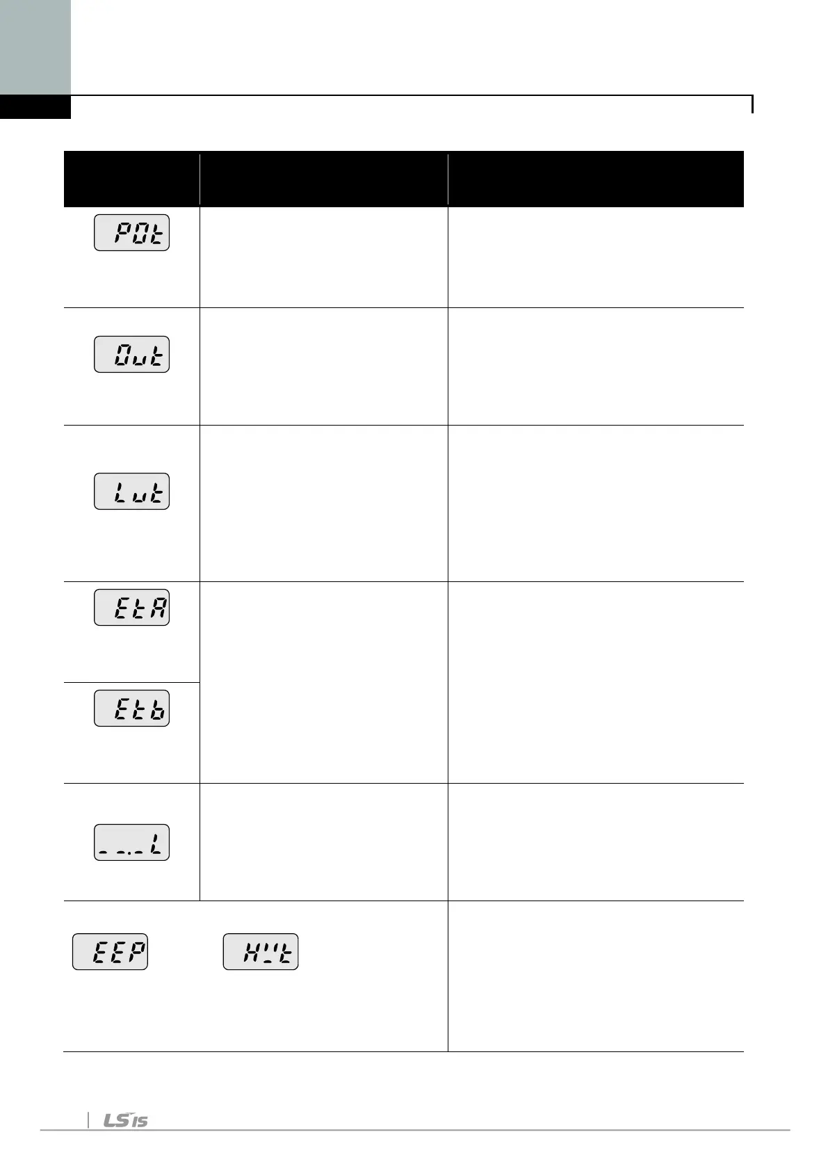
Output Phase
loss
magnetic switch at output
Faulty output wiring
Make connection of magnetic
switch at output of the inverter
securely.
Check output wiring.
Over voltage
compared to the inertia of
the load(GD
2
).
Regenerative load is at
the inverter output.
Line voltage is too high.
Check whether line voltage
exceeds its rating.
Low voltage
Load larger than line
capacity is connected to
line (ex: welding machine,
motor’s direct input)
Faulty magnetic switch at
the input side of the
Check whether line voltage is
below its rating.
Check the incoming AC line.
Adjust the line capacity
corresponding to the load.
Change a magnetic switch.
External fault A
contact input
terminals(P66 ~ P70) set
to “18 (External fault-A)” or
“19 (External trip signal
input : fault-B)” in
P66~P70 in PG Group is
ON.
Eliminate the cause of fault at
circuit connected to external
fault terminal or cause of
external fault input.
External fault
B contact input
is applied to AI terminal.
Communication
command is cuts off
Check the wiring of AI and
frequency reference level.
In case of a program set to
periodically update frequency,
check the communication line or
operation of master device.
Parameter save error Hardware fault
Contact your local LSIS sales
representative.
EEP message occurs when first
allowing power after upgrading
software due to A/S service. At
the moment, turn it off and retry.

 Loading...


