Chapter 3. Wiring
Suitable For Use On A Circuit Capable of Delivering Not More Than 5000 RMS
Symmetrical Amperes, 240 Volts Maximum. (UL508C)
Use Copper Conductors Only, 75 °C only with a torque rating. (UL508C)
Make sure the input power is off before wiring.
When the inverter’s input power is cut off after operation, wire it after DC circuit
voltage inside the inverter is fully discharged by measuring P1 and N with a
tester (voltameter). If there is no tester, wire it after the power lamp is completely
out.
Applying input power supply to the output terminals U, V and W causes internal
inverter damage.
Use ring terminals with insulated caps when wiring the input power and motor wiring
Do not leave wire fragments inside the inverter. it can cause faults, breakdowns
and malfunctions.
Never short P1 or P with N. Shorting terminals may cause internal inverter damage.
Do not connect static condenser, surge killer or radio noise filter to the output of
the inverter. Otherwise, the inverter’s protection function starts working or it may
cause condenser or surge suppressor broken.
The inverter is delivered that P~P1 are connected to short circuit.
3.3 Grounding Specification
Use the Type 3 grounding method (Ground impedance: Below 100Ω).
Use the dedicated ground terminal to ground the inverter. Do not use the screw
in the case or chassis, etc for grounding.
Note
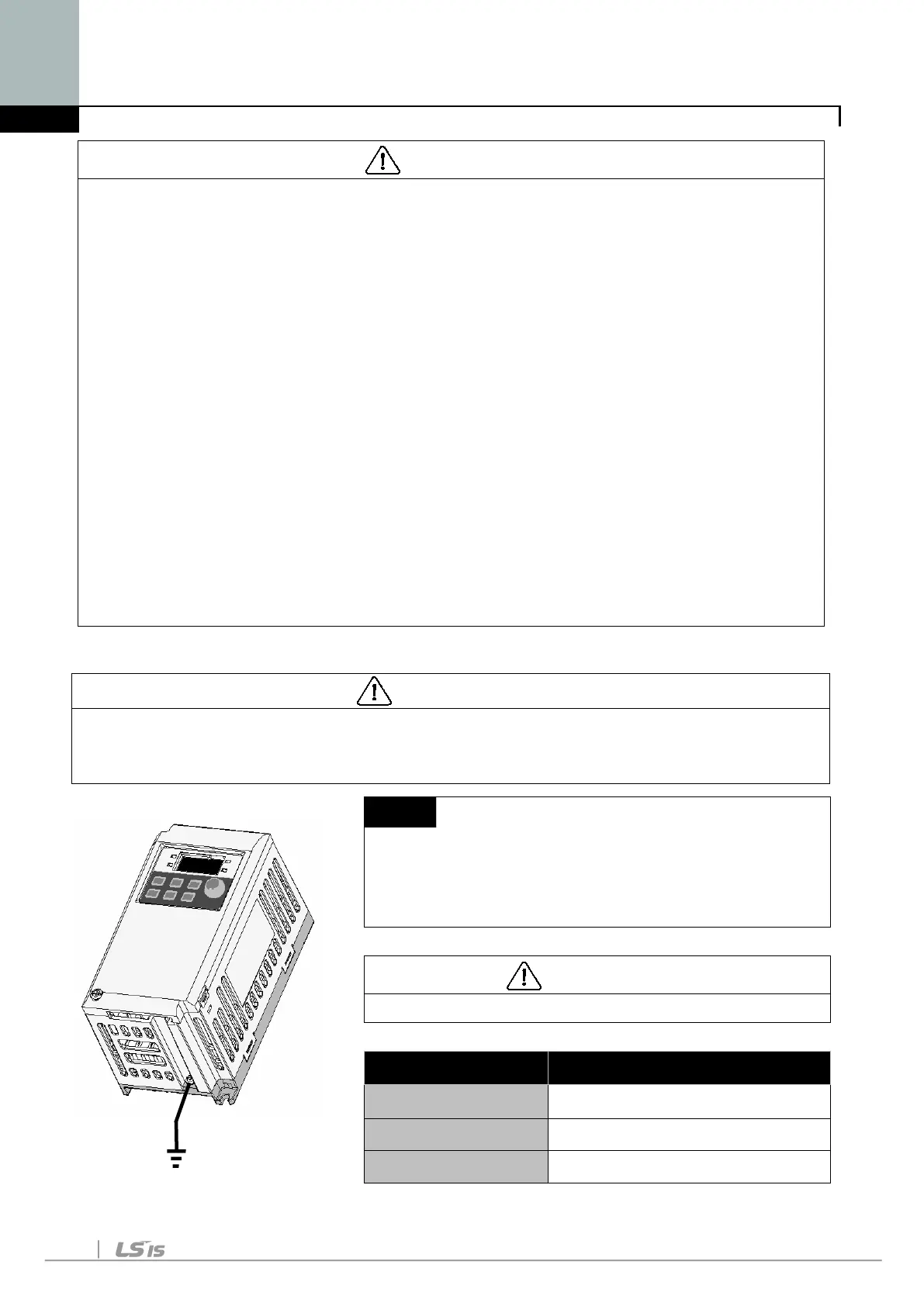
Grounding procedure
1) Remove the front cover.
2) Connect the Grounding wire to the ground
CAUTION
Follow the grounding specifications.
Inverter Cap. 001iE5, 002iE5,004iE5 – 1,2
Wire size 14AWG, 2mm
2
Lug spec. 14AWG, 2mm
2
, 4φ
Grounding method Special type 3

 Loading...


