Chapter 3. Wiring
3.4 Control Terminal Wiring Specification
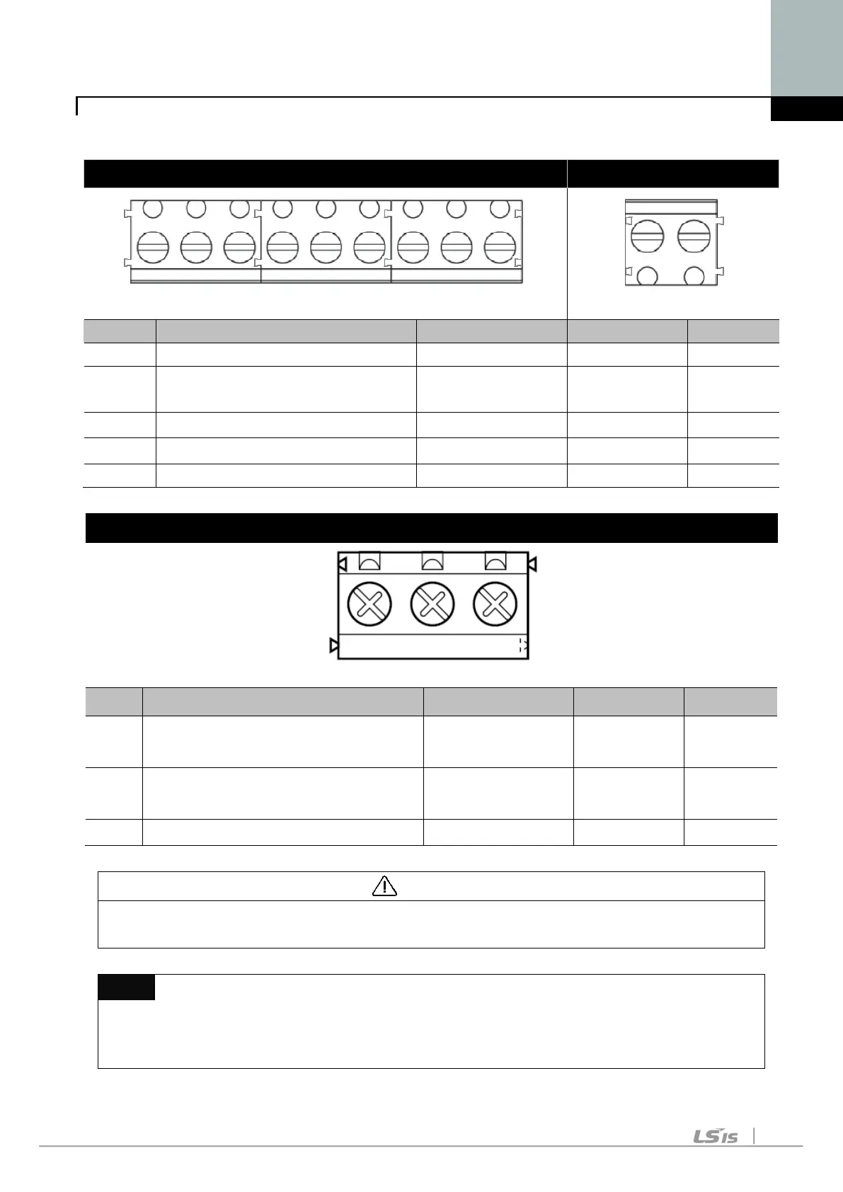
Terminal description COM optional terminal
P1 P2 P3 P4 P5 VR AI AM CM
S+ S-
Multi-function input T/M 1-5
VR
Power T/M for external volume
22 AWG,0.3 mm
2
3.0 -
Analogue frequency input T/M
AM Multi-function output T/M 22 AWG,0.3 mm
3.0 -
Multi-function Relay T/M Spec.
T/M Terminal description Wire size Torque[lb-in] Remarks
30A
Multi-function relay output A
contact
20 AWG,0.5 mm
2
4.5 -
30B
Multi-function relay output B
contact
20 AWG,0.5 mm
2
4.5 -
30C Common for Multi-function relays 20 AWG,0.5 mm
4.5 -
CAUTION
Tie the control wires more than 15cm away from the control terminals.
Otherwise, it interferes with front cover reinstallation.
Note
When you use external power supply (24V) for multi-function input terminal
(P1~P5), terminals will be active above 12V level. Take caution not to drop the

 Loading...


