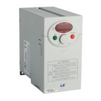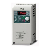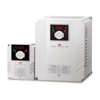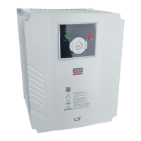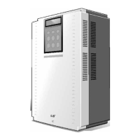
Do you have a question about the LS Industrial Systems SV-iV5 Series and is the answer not in the manual?
| Category | Inverter |
|---|---|
| Series | SV-iV5 |
| Output Voltage | 0-Input Voltage |
| Output Frequency | 0.1-400Hz |
| Frequency Range | 0.1-400Hz |
| Control Method | V/F control, Sensorless vector control |
| Overload Capacity | 150% for 60 seconds |
| Braking Unit | Built-in |
| Protection Functions | Overcurrent, Overvoltage, Undervoltage, Overheat, Ground fault |
| Communication | RS485 (Modbus RTU) |
| Cooling Method | Fan Cooling |
| Operating Temperature | -10°C to +50°C |
| Storage Temperature | -20°C to +65°C |
| Humidity | 5~95% RH (Non-condensing) |
| Altitude | Up to 1000m without derating |
Symbol indicating instant death or serious injury if instructions are not followed.
Symbol indicating possibility of death or serious injury if instructions are not followed.
Symbol indicating possibility of injury or damage to property.
Guidelines for safely carrying, installing, and handling the inverter.
Precautions related to connecting capacitors, surge filters, and radio noise filters.
Instruction to check parameters before initiating trial operation.
Guidelines for operation, including retry function, stop key usage, and alarm reset.
Highlights core capabilities like vector control, auto-tuning, and encoder error detection.
Explains the details on the inverter's nameplate and model designation.
Detailed electrical specifications for 200V and 400V AC power input types.
General specs: inverter type, control method, accuracy, braking, input/output, environment.
Advises on location, ambient temperature, material, humidity, and dust.
Diagrams for AC and DC power input types, main power, and control circuits.
Details terminal arrangements for AC power input types across different models.
Explains the function and description of power circuit terminals for AC and DC input types.
Crucial warnings for power wiring, capacitors, cable lengths, and wire size recommendations.
Specifies wire sizes for main circuits and grounding based on inverter capacity and standards.
Explains keypad layout, keys, and LED indicators for inverter operation.
Details the LCD display for start-up and group displays, showing functions and descriptions.
Guides on setting parameters via keypad, including saving changes.
Lists and describes the 12 data groups for easy access via keypad.
Explains auto-tuning importance, types, motor/encoder parameter setup, and procedures.
Explains how to check forward and reverse rotation.
Describes keypad operations for motor rotation, forward/reverse runs, and abnormal rotation causes.
Details parameter settings and wiring for operation via control terminals.
Lists display codes, names, LCD, range, default for motor status, PID, faults.
Details jump codes, multi-function input/output terminals.
Covers jump codes, initialization, motor parameters, encoder settings, and auto-tuning.
Lists function codes for speed sources, stop modes, multi-step speeds, accel/decel times, and thermal selection.
Details control modes, ASR, PID, draw, droop, torque, and speed search settings.
Explains jump codes, macros, and user code definition.
Parameters for controlling a second motor, including speed, encoder, and acceleration/deceleration.
Covers jump codes and multi-function analog input/output definitions and settings.
Explains DIS_00 (motor status), DIS_01-03 (user displays), DIS_04 (PID), DIS_05 (faults), DIS_06 (user group).
Details jump codes and multi-function input terminal definitions (P1-P7).
Explains Speed-L/M/H, JOG, MOP, and Analog Hold functions using multi-function inputs.
Explains accel/decel patterns, times, S-curve ratios, zero speed deceleration, and pre-excitation.
Covers functions for protecting the motor from overheating without external thermal relays.
Settings for inverter switching frequency and power-on start behavior.
Configuration for automatic restart after faults and delay times.
Settings for wait time, overspeed detection, and brake opening/closing.
Settings for battery-operated mode, including speed and voltage.
Details control modes, ASR, PID, draw, droop, torque, and speed search settings.
Explains PID controller enable/disable, reference source, gains, limits, and output LPF.
Functions for draw control, droop control characteristics, and torque control modes.
Settings for torque current reference, torque bias, and balance.
Functions for restarting the motor during coasting and managing user groups.
Parameters for second motor control and analog input/output configurations.
Instructions on how to enter WEB control mode via keypad and CON_02 setting.
Describes the home screen and parameter groups available in WEB Control.
Outlines compulsory and optional parameter settings for WEB control.
Settings for initializing and computing diameter using various methods.
Parameters for tension disable, maximum motor speed, and minimum effective line speed.
Configurations for winder operation and tension control methods.
Parameters for PID reference type, dancer position, PID gains, and controller types.
Functions for detecting web breakage and judging speed deviations.
Settings for emergency quick stop and jog operation modes.
General safety precautions for maintenance and inspection steps.
Guidelines for regular checks and replacement of components like cooling fans and capacitors.
Lists protective functions, keypad displays, and how to monitor current and previous faults.
Procedures for resetting the inverter and troubleshooting common issues.
Steps for diagnosing and resolving problems with motor rotation and speed.
Addresses issues like motor speed not increasing, reverse rotation, and keypad malfunctions.
Installation and wiring guide for the encoder division option board.
Setting the division ratio for monitoring encoder pulse signals.
Lists specifications for MCCBs, ELBs, contactors, and wiring.
Specifications for AC input fuses, AC reactors, and DC reactors.
Guidance on selecting dynamic braking resistors, units, and wiring temperature sensors.
Provides dimensional data for MD type inverters in mm and inches.
Dimensional data for various AC and DC power input models (SV055-220).
Dimensional data for SV300-1600 series inverters.
Dimensional data for SV2200 series inverters.
Dimensional data for SV2800-3750 series inverters.
High-level overview of the inverter's control system architecture.
Block diagram for analog input setpoint settings, gain, and bias.
Control block diagram for frequency and speed settings with multi-function inputs.
Block diagram illustrating the drive sequence based on RUN/STOP sources and rotation.
Block diagram for acceleration/deceleration routines and parameter selections.
Block diagram for command control, including droop and PID settings.
Block diagram of the speed control loop with ASR and related parameters.
Diagram showing torque reference, limit settings, and bias.
Block diagram for flux reference, field weakening, and motor parameters.
Block diagram illustrating angular velocity calculation and its relation to control.
Diagram of motor control, including voltage/current transformations and PI control.
Diagram showing MFi output signals based on input and detection parameters.
Declaration of conformity with EU directives for electrical equipment and EMC.
Cites applied standards like EN 61800-3 and EN 50178 for compliance.
Steps for installing RFI filters to meet EMC directive requirements.
Dimensional drawings and wiring guidelines for FF and FE series filters.
Guidance on contacting LS for defective parts within the guarantee period.
Lists cases where the warranty is voided, even within the guarantee term.
Lists revision numbers, dates, editions, and changes made to the manual.
Notes on environmental preservation and product disposal guidelines.
