3. Installation and Wiring
3-9
(2) DC power input type
Name Function Description
P(+), N(-) DC input power source
Connected to DC input power source
Connected from DC power suupy (PWM converter) within
max. 30m
U, V, W Inverter Output Connected to 3-phase induction motor
G Grounding Used for inverter frame earth
FAN1,
FAN2
Internal cooling fan and MC
drive power source
Connected to single-phase 220V AC power source
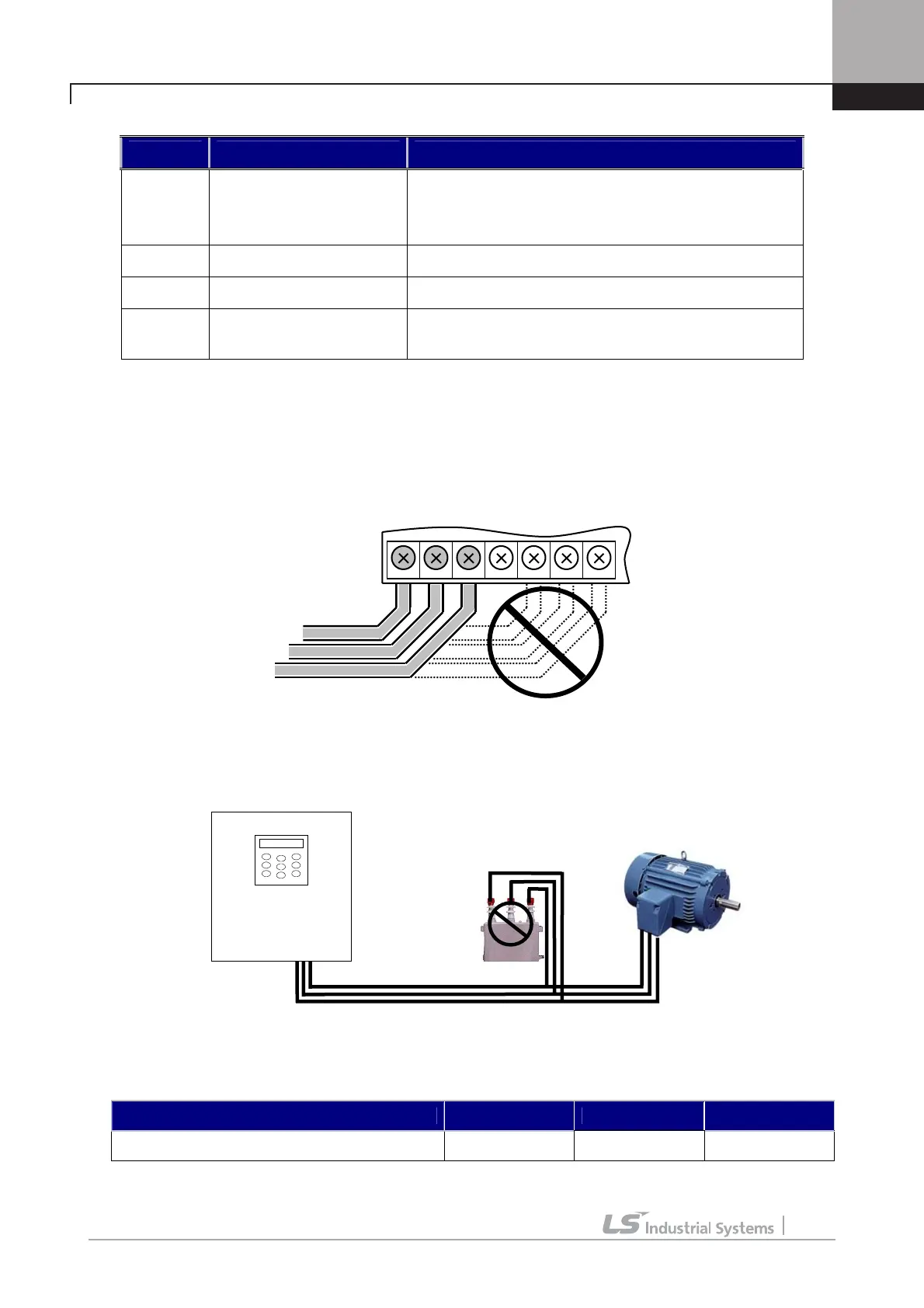
3.3.3 Cautions to be required for wiring to power circuit terminal
① Connect terminals ( R, S and T) to 3 phase input power supply after checking inverter nameplate
attached on the inverter. Never connect terminals (U, V and W) to 3 phase input power supply. It results in
lethal damage to the inverter.
② Never connect the phase advancing capacitor to the inverter output. If already installed, remove the
phase advancing capacitor clearly.
③ Cable between inverter output and motor should be less than 30m long. If cable gets long, surge voltage
appears across motor terminals depending on the cable parameters. Especially, in 400V class motor case,
insulation withstanding voltage may be decreased. Use an insulation-enforced motor when 400V class motor
is used.
Distance between inverter and motor Up to 50m Up to 100m Over 100m
Permitted Carrier Frequency Below 10kHz Below 5kHz Below 2.5kHz
(In case of below 3.7 kW, use the cable of output within 100 m)
Input
Voltage
R S T G U V W
Phase
advancing
capacitor
SV-iV5

 Loading...


