3. Installation and Wiring
3-15
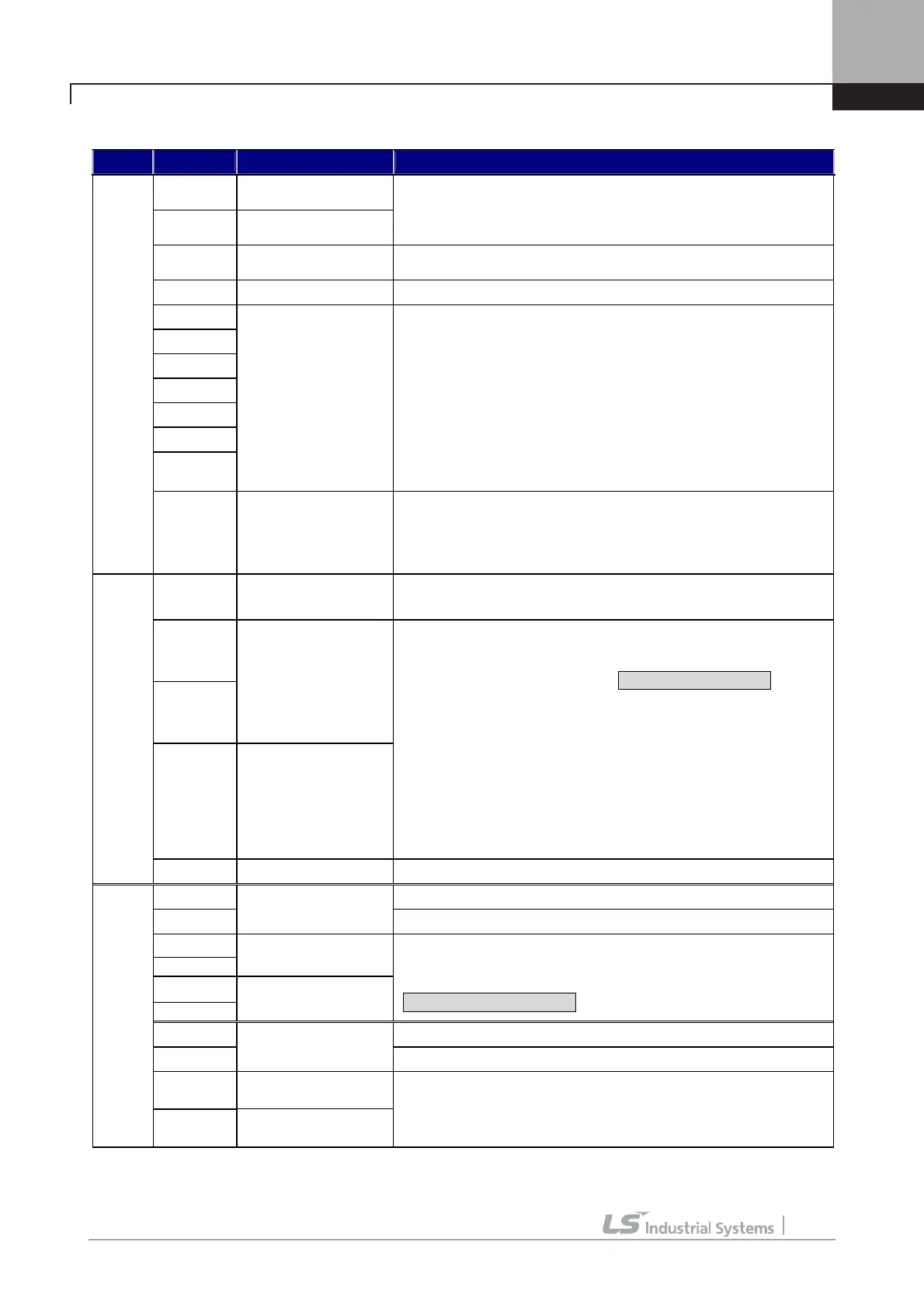
3.4.3 Control circuit terminal function description
Item Name Function Description
FX
Forward Run /Stop
Command
RX
Reverse Run/Stop
Command
z Forward/Reverse RUN Command is ON when closed to CM in NPN
input mode.
z Motor stops when FX/RX is ON or OFF at the same time.
BX Emergency Stop
z ON when closed to CM in NPN input mode, Free-run to Stop and
deceleration to stop. It does not trigger fault alarm signal.
RST Fault Reset Resets when fault condition is cancelled.
P1(MM0)
P2(MM1)
P3(AT0)
P4(FHM)
P5(BAT)
P6(BRC)
P7(MCC)
Multi-function input
contact
z 1 function can be selected among 42 different functions shown
below.
(Multi-step speed 1 / 2 / 3, Jog, MOP Up / Down / Save
/ Clear, Analog Hold, Main Drive, 2nd function, Accel./Decel.
Time selection, 3 Wire RUN, External trip (B contact), Power
failure prevention, Reverse rotation prevention, Process PI
Disable, Timer input, Soft start cancel, ASR P/PI Gain switch-over,
ASR P/PI switch-over, Flux command value switch-over, Pre-
excitation, Speed/Torque control, Torque limit ON/Off, Torque bias
ON/Off, Battery operation On/Off, Low voltage trip detection
prevention)
Contact Input
CM COMMON
z In NPN input mode, it turns On when each contact is closed to CM
terminal.
z In PNP input mode, it turns On when each contact is closed to
external 24V input.
VREF
Power supply for
analog setting
z Reference voltage by variable resistor ( + 10V ) : 10kΩ
AI1
AI2
Voltage/ Current
Signal Input
AI3/Them
Voltage input
Motor NTC/PTC Input
z Voltage input (-10Æ10V, 10Æ-10V, 0Æ10V, 10Æ0V)
current input (0Æ20mA, 20Æ0mA), Motor NTC/PTC are selectable
via Multi-function Analog input.
z Jumper setting in Voltage Input: Jumper set as default)
Î AI1, AI2: Jumper set on left side,
AI3: Switch set on left (“V”) side
z Jumper setting in Current Input
Î AI1, AI2: Jumper set on right side
z S/W setting in motor NTC (OTIS motor)/PTC input
Î AI3: switch set on right (“Them”) side.
z Selectable 15 functions as following:
(Speed, Process PID controller, Process PI controller feedback,
Draw, Torque, Magnetic flux, Torque bias, Torque limit, Motor
NTC/PTC…)
Analog Input
5G COMMON z COMMON terminal for Analog input
PE +5V Line Drive Power
GE
P/S (Power supply)
for Pulse Encoder
1)
0V
A+
A-
Encoder A-phase
signal
B+
B-
Encoder B-phase
signal
z A, B signal for Line Drive Type Encoder.
z Set the JP2 switch at “P5” on I/O PCB and set the JP4 switch to
“LD” for the use of Line Drive.
※ Jumper set as default
PE +15V Open Collector Power
GE
P/S for Open
Collector
Note1)
0V
PA
Encoder A-phase
signal
Encoder Input
PB
Encoder B-phase
signal
z A, B signal for Complementary or Open Collector Type Encoder.
z Set the JP2 switch at “P15” on I/O PCB and set the JP4 switch to
“OC” for the use of Open Collector.

 Loading...


