6. Function Description
6-55
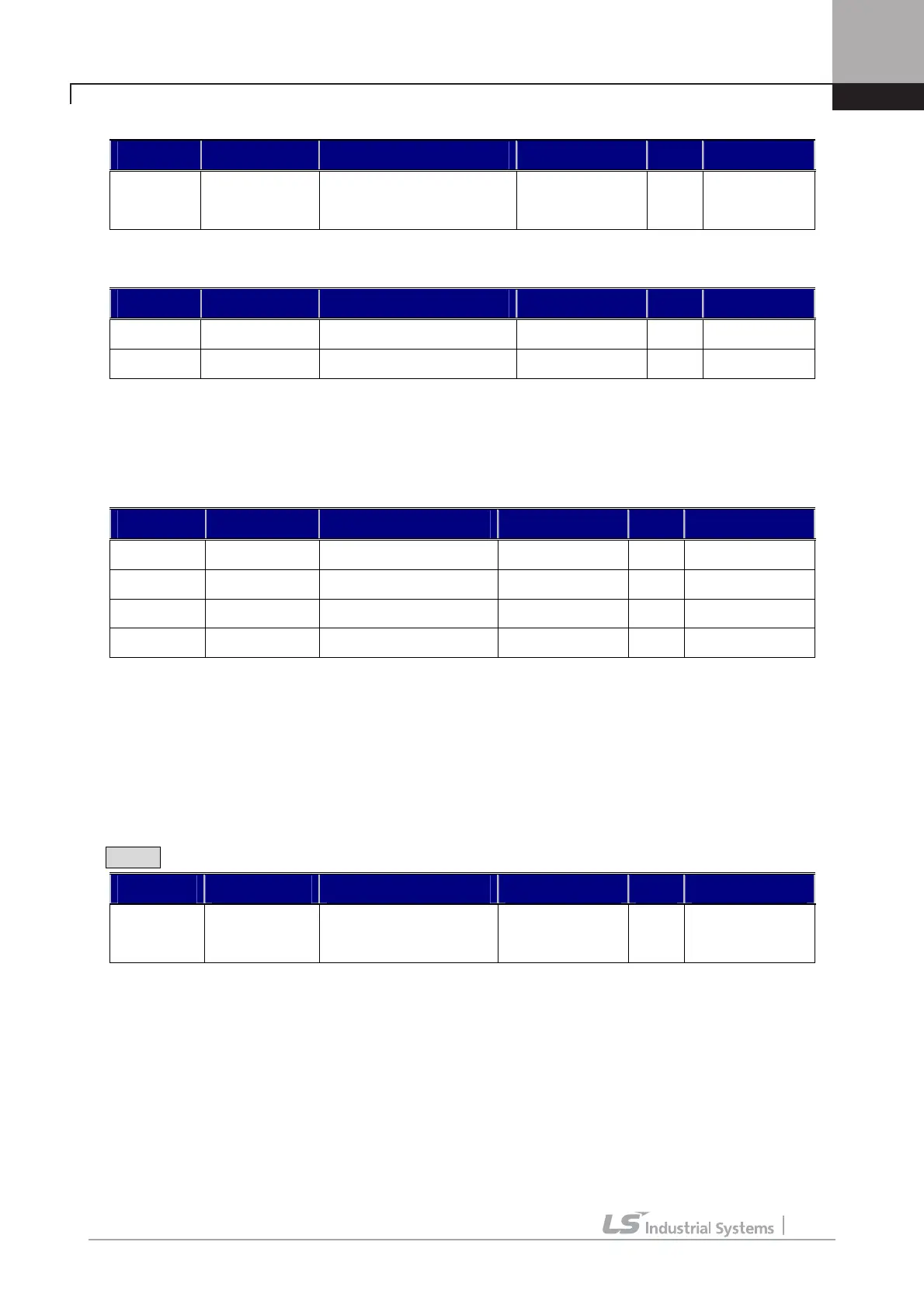
(Example) Programming P4 as ASR PI Gain
Code LCD display Description Setting range Unit Set value
DIO_04 P4 define
Multi-function input terminal
P4 definition
ASR Gain Sel
The two sets of Lowpass Filter are as follow:
Code LCD display Description Setting range Unit Factory setting
CON_05 ASR LPF1 ASR LPF time constant 1 0 ~ 20000 ms 0
CON_08 ASR LPF2 ASR LPF time constant 2 0 ~ 20000 ms 0
3)
CON_03 ~ 04(ASR PI Gain 1)
4) CON_06 ~ 07(ASR PI Gain 2)
One of 2 sets of PI gain can be selected by “ASR Gain Sel” in Multi-function input terminal.
Code LCD display Description Setting range Unit Factory setting
CON_03 ASR P Gain1 ASR P Gain 1 0.0 ~ 200.0 % 50.0
CON_04 ASR I Gain1 ASR I Gain 1 0 ~ 50000 ms 300
CON_06 ASR P Gain2 ASR P Gain 2 0.0 ~ 200.0 % 5.0
CON_07 ASR I Gain2 ASR I Gain 2 0 ~ 50000 ms 3000
5) CON_09 (Ramp time for ASR gain Transfer)
6) CON_10 (Motor Speed at the time of ASR Gain Transfer)
ASR PI controller can be transferred to P controller depending on the status of the multi-function terminal input set
as ’ASR P/PI transfer’.
Example When P6 is set to ASR P/PI transfer:
Code LCD display Description Setting range Unit Factory setting
DIO_06 P6 define
Multi-function input
terminal P6 definition
ASR P/PI Sel
To avoid the shock to the control system due to the rapid change P and I gain in case of ASR gain transfer, if the
multi-function terminal input set to ‘ASR Gain Sel’ is ‘On’, the transferred P gain changes gradually for the time set at
CON_09. P gain 2 is transferred to P gain 1 at the higher speed than the value set at CON_10. This happens when the
multi-function terminal input set to ‘ASR Gain Sel’ is ‘On’, not ‘Off”

 Loading...


