9. Troubleshooting and Maintenance
9-3
9.2.2 Monitoring previous faults
z Previous 2 faults are saved in DIS_05 “Last fault 1/2“. Last fault 1 is more recent fault than Last fault 2.
Refer to “8.2.1 monitoring fault display” to check the fault contents.
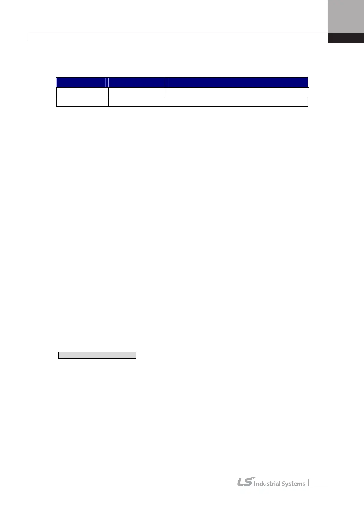
Code LCD display Description
DIS_05 Last Fault1 Previous fault 1
DIS_05 Last Fault2 Previous fault 2
z DIS_05 “ Fault Clear” removes Last Fault1, Last Fault2 data. It becomes the value of factory
defualt.
9.3 Fault Reset
There are 3 ways to reset the inverter. After performing this, the number of automatic restart is initialized.
1) Use [RESET] key on the keypad.
2) Short the RST-CM terminal to reset.
3) Cycle the power (turn the power OFF and turn it ON).
9.4 Fault Remedy
9.4.1 Check the below diagnosis before troubleshooting.
1) Is the wiring of a motor and an inverter conducted correctly?
☞ Refer to Main Circuit Terminal
2) Is the Encoder-type jumper on I/O PCB set correctly?
☞ Refer to Encoder wiring
If encoder type is either Complementary or Open collector, slide JP4 switch to “OC” and slide JP2 switch to
“P15”. If encoder type is Line Drive, slide the JP4 switch to “LD” and slide JP2 switch to “P5”.
Factory default: Line Drive Type
3) Is motor rotating direction set correctly?
☞ Refer to Monitoring Encoder operation. (Refer to 4-10p.)
STARVERT
-
iV5 defines Forward rotation when motor rotates in clockwise from the view of Rear
Bracket (Motor FAN).
4) Is inverter operating correctly in no load condition?
☞ Refer to Operation via Keypad and Control Terminal

 Loading...


