Chapter 6. Basic Operation
6. Basic Operation
6.1 Frequency Setting and Basic Operation
Note
The following parameters are set to factory defaults. Therefore, results may be
different if any parameter is changed by a user. In this case, initialize parameters back
to factory defaults and follow the instructions below.
If setting frequency with the loader and commanding operation on the inverter’s
terminal
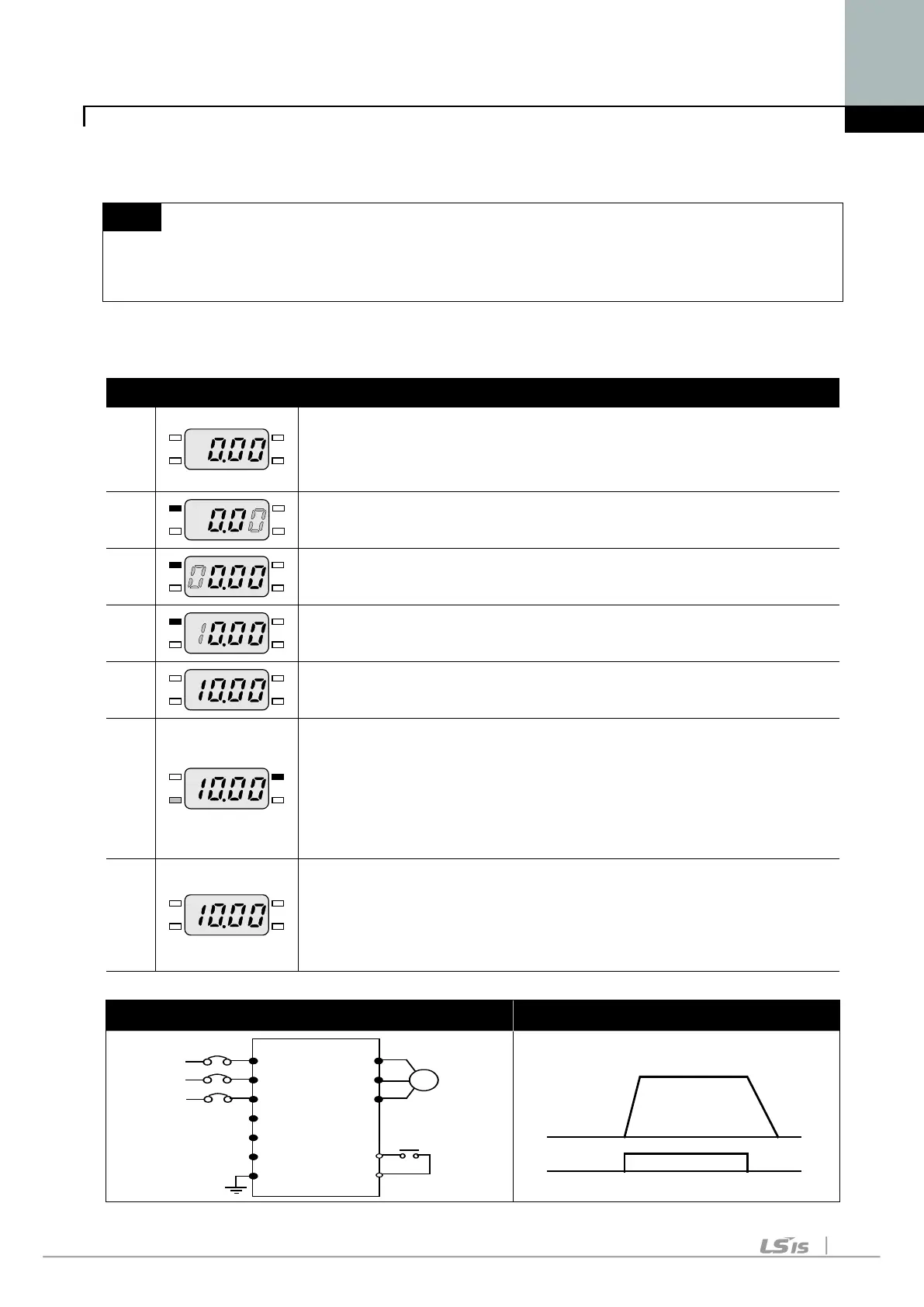
No. Indication Operation and description
1
-
. Target frequency, the first code of Drive Group when
turning it on.
-. Press FUNC key.
2
-. The second decimal, 0 in 0.00 displayed blinks.
-. Press SHFT three times.
3
-. 00.00 is displayed and the very left 0 blinks.
-. Press UP() key.
4
-. Confirming 10.00, press FUNC key.
-.
10.00 blinks quickly as a whole. Press FUNC key once more.
5
-. Target frequency is changed to 10.00Hz.
-. Turn on the switch between P1(FX) and CM terminals.
6
-. FWD(forward run) lamp of the inverter display blinks and
accelerating frequency is displayed on the LED.
-. When target run frequency 10Hz is reached, 10.00 is
displayed.
-. Turn off the switch between P1 (FX) and CM terminals.
7
-. FWD lamp begins to blink and decelerating frequency is
displayed on the LED.
-. When run frequency is reached to 0Hz, RUN and FWD
lamp turn off and target frequency (10.00) is displayed.
Wiring diagram Operating pattern
M
L1 (R)
L2 (S)
(T)
P
P1
N
G
U
V
W
P1(FX)
CM
220 Vac
Frequency
P1(FX)-CM
ON
OFF
10 Hz

 Loading...


