8-23
Selects the self drive in the 2
nd
switching of Frq2 among the followings
Frq2
Frequency mode
2
0
Digital
Keypad digital frequency mode1
1 Keypad digital frequency mode2
2
Analog
V1 terminal setting1: -10 ~ +10V
3 V1 terminal setting2: 0 ~ +10V
4 I terminal: 0 ~ 20mA
5 V1 terminal setting1 + I terminal
6 V1 terminal setting2 + I terminal
7 Setting via RS-485 communication
The following is example for switching of drv1 and drv2.
Group Display Parameter Name Setting Range Default Unit
Drive
group
drv Drive mode 1 - 0 ~ 3 1 -
Frq Frequency mode 1 - 0 ~ 8 0 -
drv2 Drive mode 2 - 0 ~ 3 1
Frq2 Frequency mode 2 - 0 ~ 7 0
I/O
group
I24
Multi-function input
terminal P8 input terminal
-
0 ~ 27
7
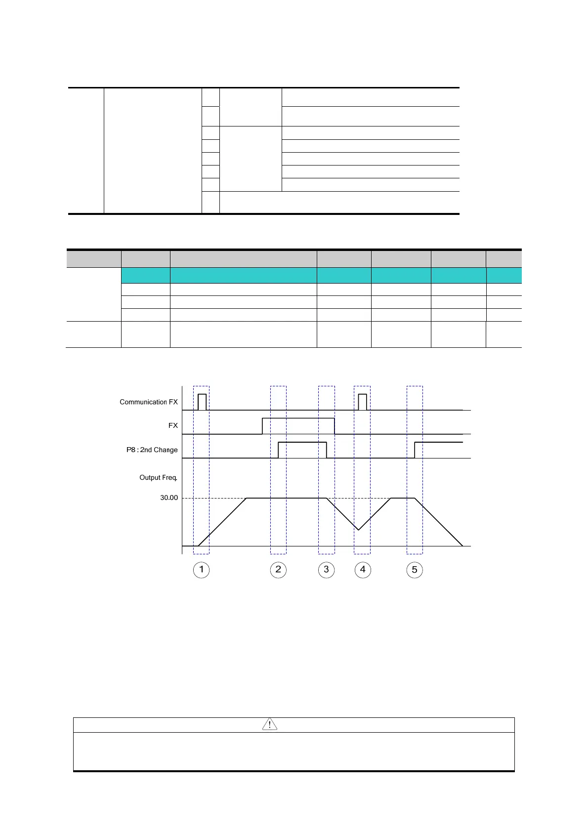
The following figure is drawn when setting is like the above and command frequency is 30 [Hz],
F4 [stop method]=0
① Accelerate for accel time up to setting frequency by Drive 1 mode, FX signal.
② Drive continuously under FX is ON because DRV2 is 1 when P8 terminal input is ON and
change into 2
nd
.
③ Stop gradually as stop command because DRV is communication drive when P8 terminal
input is OFF and change into 1st.
④ Accelerate up to setting frequency for Drive 1 mode, FX signal is ON.
⑤ Stop gradually under FX is OFF because DRV2 is 1 when P8 terminal input is ON and
change into 2
nd
.
CAUTION
If you press ON while multi-function input terminal (P1 ~ P8) is set to 2
nd
Source,
frequency command and drive command is changed to Drive mode 2. So you
should check Drive mode 2 before input multi-function terminal.

 Loading...

