9-33
CHAPTER 9 - MONITORING
9.1 Operating status monitoring
z Output current
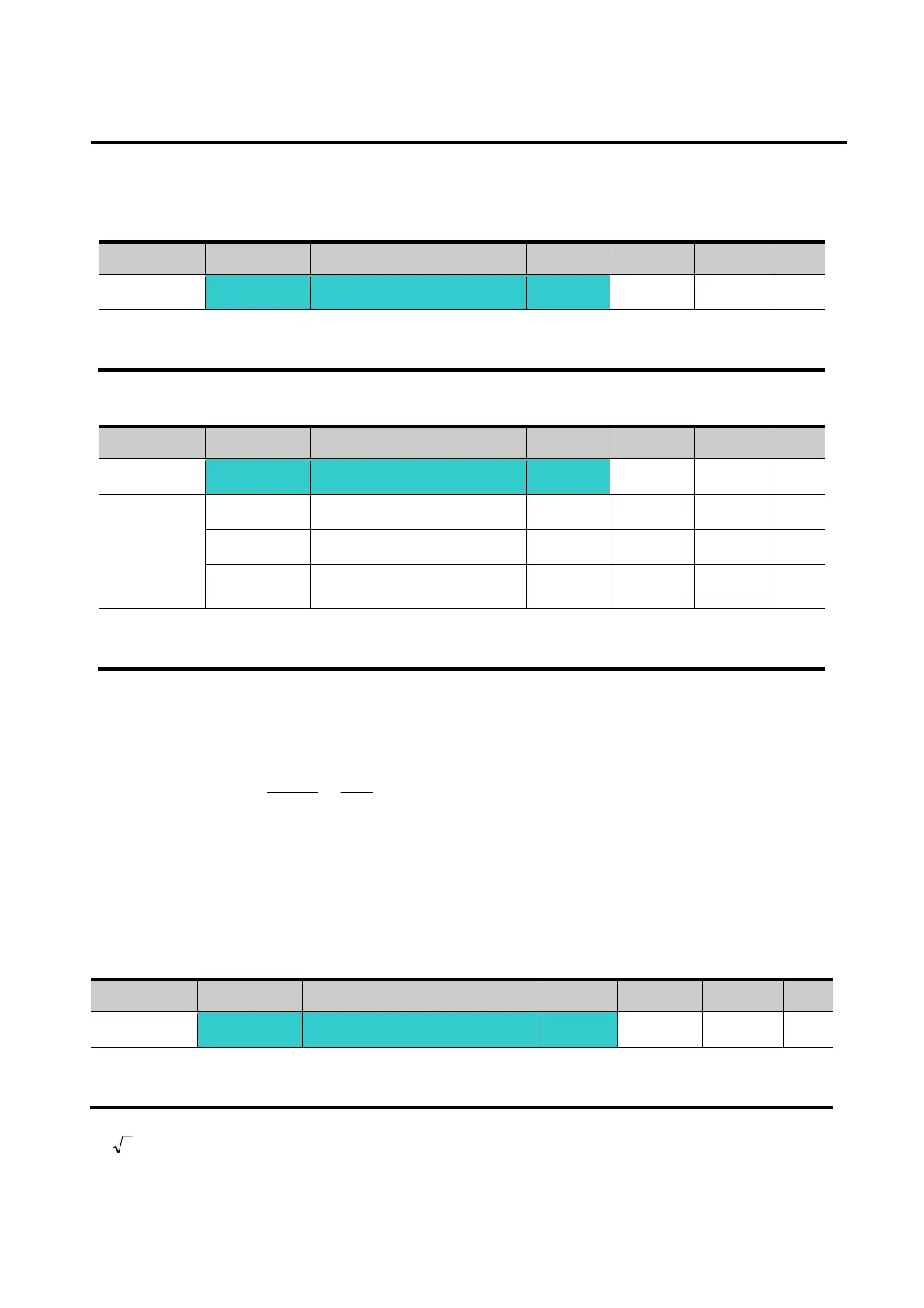
Group Display Parameter Name Setting Range Default Unit
Drive group
CUr [Output current] -
Inverter output current can be monitored in Cur.
z Motor RPM
Group Display Parameter Name Setting Range Default Unit
Drive group
rPM [Motor RPM] -
Function
group 2
H31 [Number of motor poles] - 2 ~ 12 4
H49 [PID control select] - 0 ~ 1 0
H74
[Gain for Motor rpm
display]
- 1 ~ 1000 100 %
Motor rpm can be monitored in rPM.
When H40 is set to 0 {V/F control} or 1 {PID control}, the Inverter output frequency (f) is
displayed in RPM using the formula below. Motor slip is not considered.
In case that H49 code is 1, Feed back amount is converted into frequency.
H31: Enter the number of rated motor poles on the nameplate.
H74: This parameter is used to change the motor speed display to rotating speed (r/min) or
mechanical speed (m/min).
z Inverter DC Link Voltage
Group Display Parameter Name Setting Range Default Unit
Drive group
dCL [Inverter DC Link Voltage] -
Inverter DC link voltage can be monitored in dCL.
2 times the value of input voltage is displayed while motor is at a stop.
100
74
31
120
H
H
f
RPM ×
⎟
⎠
⎞
⎜
⎝
⎛
×
=

 Loading...

