8-24
8.17 Over voltage trip prevention deceleration and Power Braking
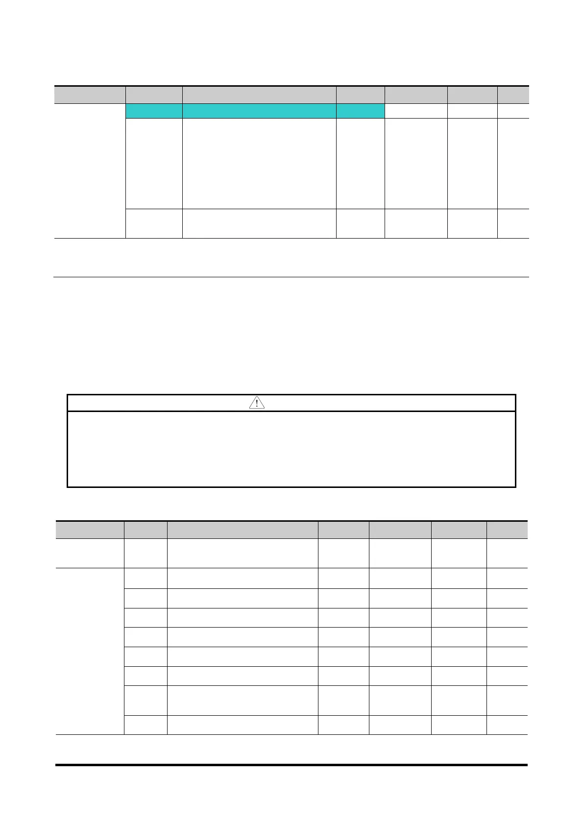
Group Display Parameter Name Setting Range Default Unit
Function
group 1
F 4 Select stop method 3 0 ~ 3 0
F 59 BIT 0: stall prevention
under Accel
BIT 1: stall prevention
under constant speed
BIT 2: stall prevention
under Decel
- 0 ~ 7 0
F 61
Select voltage limit under
Decel
- 0 ~ 1 0
To prevent overvoltage trip when reducing speed, set BIT2 of F59 to 1 and set 3 of F4 for
Power Braking.
Overvoltage trip prevention when reducing speed: a function preventing overvoltage trip when
reducing speed or at stop by using the regeneration braking power.
Power Braking : Adjusting the deceleration slope or accelerate again, when inverter’s DC
voltage rises above a certain level by the electric motor’s regeneration energy. It can be used
when short deceleration time without braking resistance is needed. However, be aware that the
deceleration time can get longer than the set one and when it’s used at a load that frequently
decelerates, be cautious of damage caused by the motor’s over heating.
Caution
Stall prevention and Power Braking only operate when decelerating, and Power
Braking has the precedence. That is, when BIT2 of F59 and Power Braking of F4 are
both set, Power Braking operates.
F61(selecting voltage restriction when decelerating) is visible when BIT2 of F59 is
set.
Overvoltage trip may occur, if the deceleration time is too short or the inertia too big.
8.18 External brake control
Group Code Name Set nr.
Limit Default Unit
Function
Group 2
H 40 Controlling method select
0 0~3 0
In/Output
Group
I 82 Brake open current - 0~180.0 50.0 %
I 83 Brake open delay time - 0~10.00 1.00 Sec.
I 84 Brake open CW Freq. - 0~400 1.00 Hz
I 85 Brake open CCW Freq. - 0~400 1.00 Hz
I 86 Brake close delay time - 0~10.00 1.00 Sec.
I 87 Brake close Freq. - 0~400 2.00 Hz
I 54
Multi-function output
terminal select
19 0~ 19 12
I 55 Multi-function relay select
19 0~ 19 17
I82~87 is visible only when I 54 or I 55 is set to 19.

 Loading...

