2-7
2.3 Terminal wiring (Control I/O)
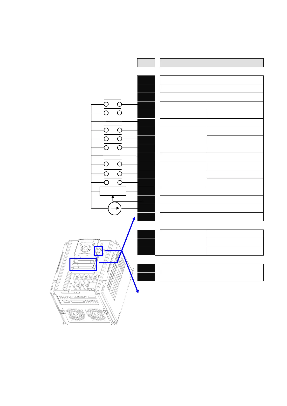
T/M Description
MO
Multi-function open collector output
MG
MO Common
24
24V output
P1
MF input terminal
(factory setting)
FX: Forward run
P2
RX: Reverse run
CM
Input signal common
P3
MF input terminal
(factory setting)
BX: Emergency stop
P4
RST: Trip reset
P5
JOG: Jog operation
CM
Input signal common
P6
MF input terminal
(factory setting)
Multi-step freq.-Low
P7
Multi-step freq.-Middle
P8
Multi-step freq.-High
VR
10V power supply for potentiometer
V1
Freq. Setting Voltage signal input: -0~10V
I
Freq. Setting Current signal input: 0~20mA
AM
Multi-function analog output signal: 0~10V
3A
Multi-function relay
output terminal
A contact output
3B
B contact output
3C
A/B contact common
S+
RS485 communication terminal
S-
※ For connection to Remote Option or
parameter copying

 Loading...

