5-1
CHAPTER 5 - FUNCTION LIST
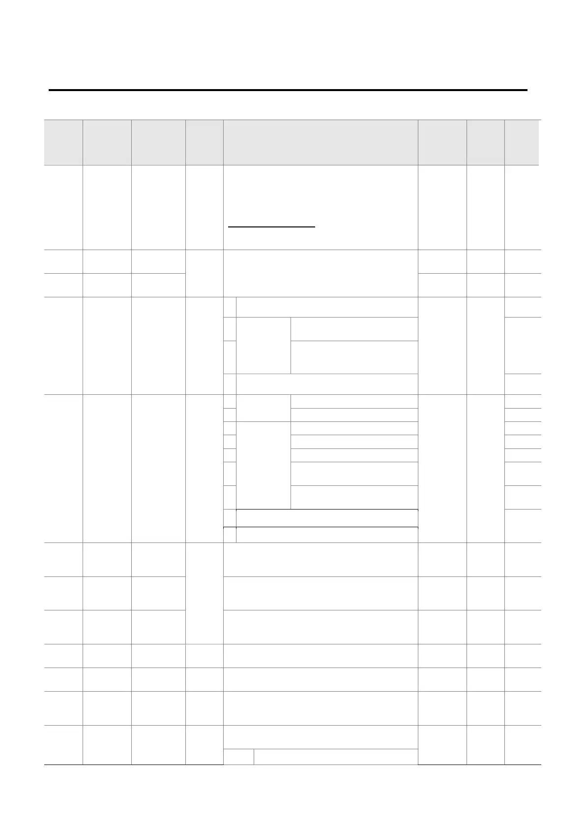
z Drive Group
LED
display
Address
for
communi
cation
Parameter
name
Min/M
ax
range
Description
Factory
defaults
Adj.
during
run
Page
0.00
A100 [Frequency
command]
0 ~
400
[Hz]
This parameter sets the frequency that the
inverter is commanded to output.
During Stop: Frequency Command
During Run: Output Frequency
During Multi-step operation:
Multi-step frequency 0
.
It cannot be set greater than F21- [Max
frequency].
0.00 O 7-1
ACC A101 [Accel
time]
0 ~
6000
[Sec]
During Multi-Accel/Decel operation, this
parameter serves as Accel/Decel time 0.
5.0 O 7-12
dEC A102 [Decel
time]
10.0 O 7-12
drv A103 [Drive
mode]
0 ~ 3
0
Run/Stop via Run/Stop key on the keypad 1 X 7-8
1
Terminal
operation
FX: Motor forward run
RX: Motor reverse run
7-8
2
FX: Run/Stop enable
RX: Reverse rotation select
3
RS485 communication 7-9
Frq A104 [Frequency
setting
method]
0 ~ 7 0 Digital Keypad setting 1 0 X 7-1
1 Keypad setting 2 7-1
2
Analog
V1 1: -10 ~ +10 [V] 7-2
3 V1 2: 0 ~ +10 [V] 7-3
4 Terminal I: 0 ~ 20 [mA] 7-4
5
Terminal V1 setting 1 +
Terminal I
7-5
6
Terminal V1 setting 2+
Terminal I
7-6
7
RS485 communication 7-5
8
Digital Volume
St1 A105 [Multi-Step
frequency
1]
0 ~
400
[Hz]
Sets Multi-Step frequency 1 during Multi-step
operation.
10.00 O 7-7
St2 A106 [Multi-Step
frequency
2]
Sets Multi-Step frequency 2 during Multi-step
operation.
20.00 O 7-7
St3 A107 [Multi-Step
frequency
3]
Sets Multi-Step frequency 3 during Multi-step
operation.
30.00 O 7-7
CUr A108 [Output
current]
Displays the output current to the motor. - - 9-1
rPM A109 [Motor
RPM]
Displays the number of Motor RPM. - - 9-1
dCL A10A [Inverter
DC link
voltage]
Displays DC link voltage inside the inverter. - - 9-1
vOL A10B [User
display
select]
This parameter displays the item selected at
H73- [Monitoring item select].
vOL - 9-2
vOL Output voltage

 Loading...

