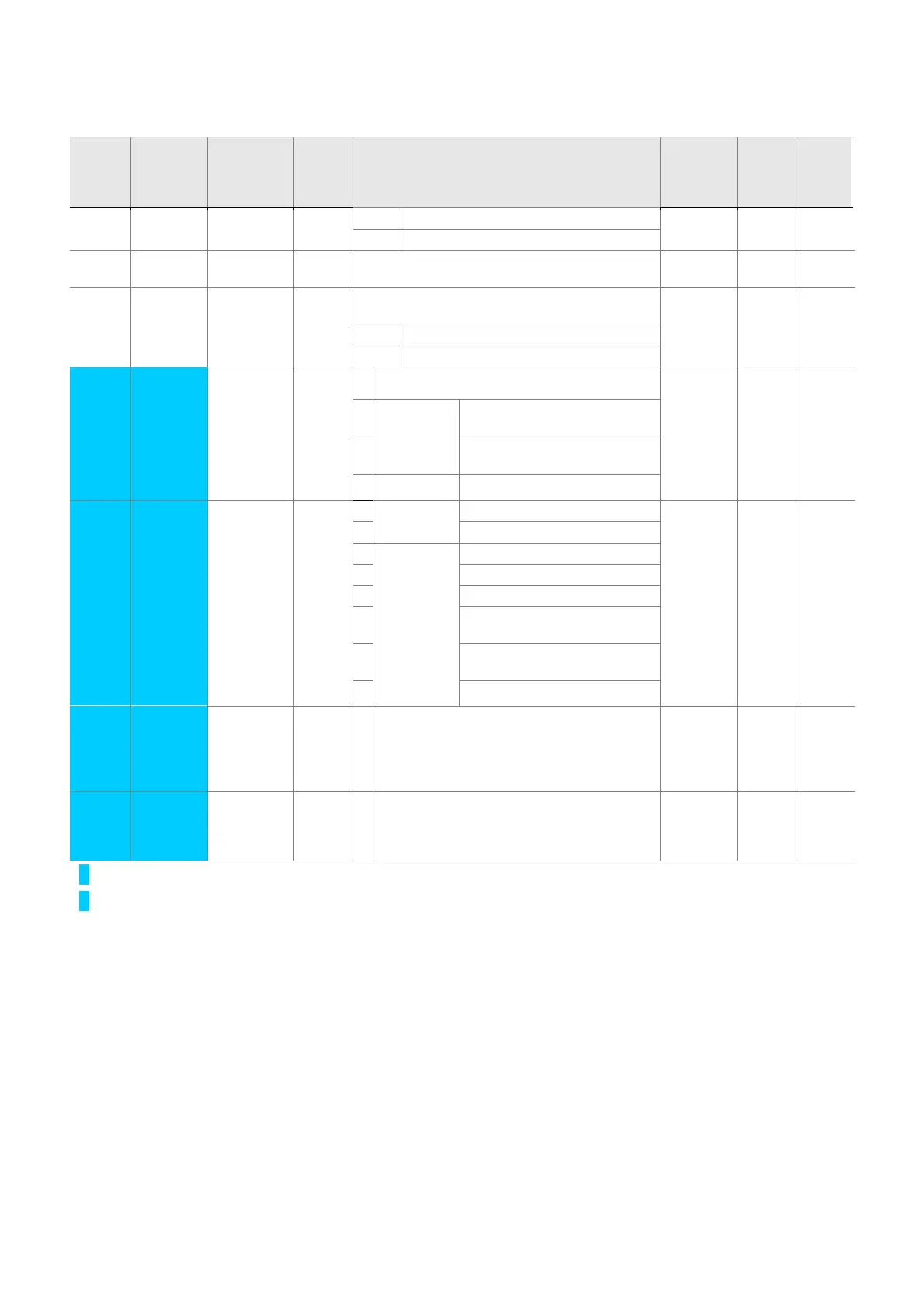
5-2
z Drive Group
LED
display
Address
for
communi
cation
Parameter
name
Min/M
ax
range
Description
Factory
defaults
Adj.
during
run
Page
POr Output power
tOr Torque
nOn A10C [Fault
Display]
Displays the types of faults, frequency and
operating status at the time of the fault
- - 9-4
drC A10D [Direction
of motor
rotation
select]
F, r Sets the direction of motor rotation when drv -
[Drive mode] is set to either 0 or 1.
F O 7-8
F Forward
r Reverse
drv2
A10E [Drive
mode 2]
0 ~ 3
0
Run/Stop via Run/Stop key on the keypad 1 X 8-24
1
Terminal
operation
FX: Motor forward run
RX: Motor reverse run
2
FX: Run/Stop enable
RX: Reverse rotation select
3
RS-485 communication
Frq2
A10F [Frequency
setting
method 2]
0 ~ 7 0 Digital Keypad setting 1 0 X 8-24
1 Keypad setting 2
2 Analog V1 1: -10 ~ +10 [V]
3 V1 2: 0 ~ +10 [V]
4 Terminal I: 0 ~ 20 [mA]
5
Terminal V1 setting 1 +
Terminal I
6
Terminal V1 setting 2+
Terminal I
7
RS-485 communication
rEF
A110 PID control
standard
value
setting
0~400
[Hz] or
0~100
[%]
If H58 is 0, it is expressed as a [Hz] unit.
If H58 is 1, it is expressed as a [%] unit.
In [Hz] unit, you can’t set Max. frequency
more than (F21).
In [%] unit, 100% means Max. frequency.
0.00 0 8-11
Fbk
A111 PID control
feedback
amount
It indicates a feedback amount in PID
control.
If H58 is 0, it is expressed as a [Hz] unit.
If H58 is 1, it is expressed as a [%] unit.
- - 8-11
1)
: Only displayed when one of the Multi-function input terminals 1-8 [I17~I24] is set to “22”.
2)
: It is indicated when H49(PID control selection) is 1.

 Loading...

