9-40
I56: When 17 {Fault display} is selected in I54 and I55, Multi-function output terminal and relay
will be activated with the value in I56.
z 0: FDT-1
Check whether the output frequency matches the user-setting frequency.
Active condition: Absolute value (preset frequency - output frequency) <= Frequency Detection
Bandwidth/2
Group Display Parameter Name Setting Range Default Unit
I/O group
I53
[Detected Frequency
Bandwidth]
-
0 ~ 400 10.00 Hz
Cannot be set above Max frequency (F21).
When setting I53 to 10.0
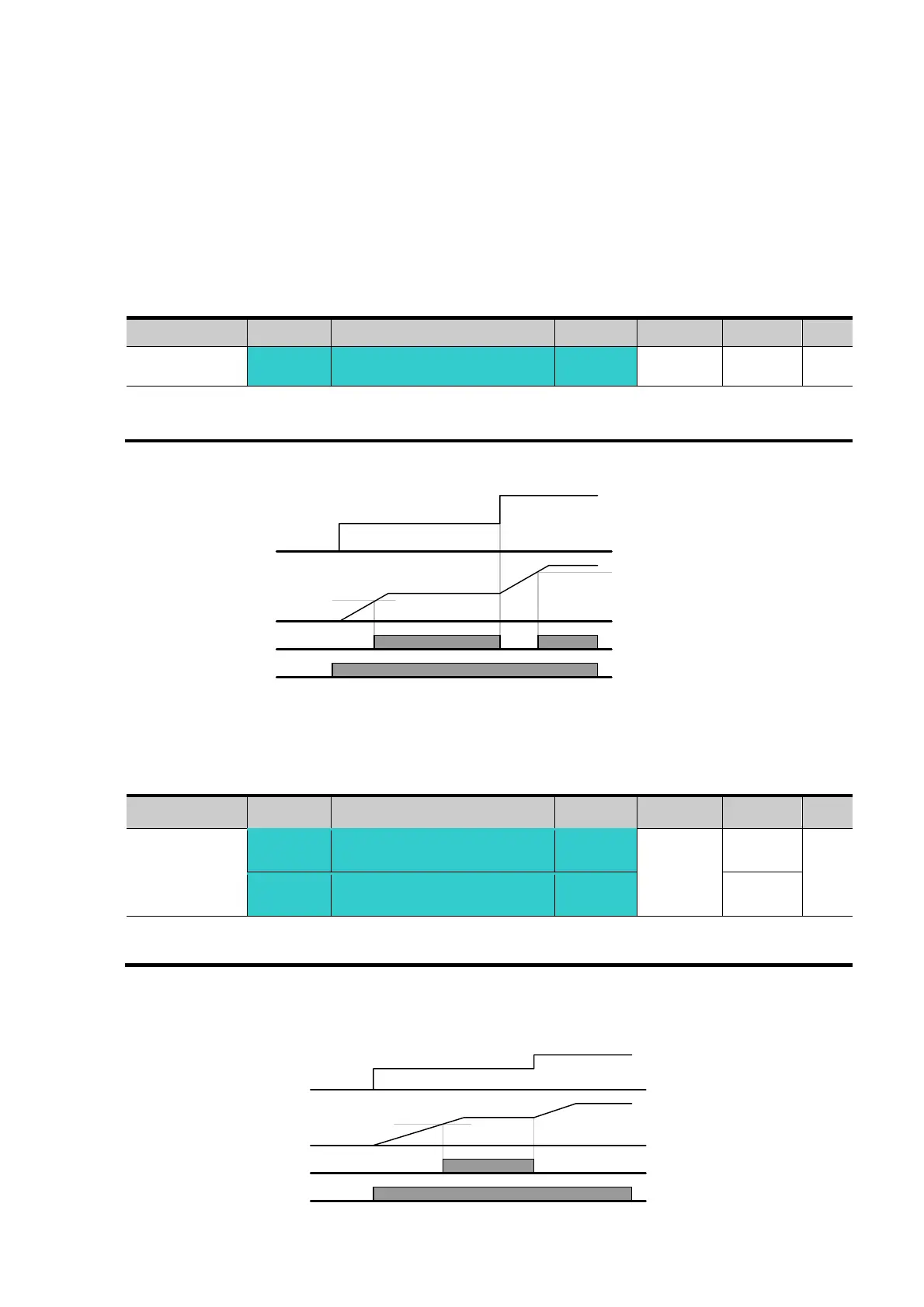
z 1: FDT-2
Activated when the preset frequency matches frequency detection level
(I52) and FDT-1 condition is met.
Active condition: (Preset frequency = FDT level) & FDT-1
Group Display Parameter Name Setting Range Default Unit
I/O group
I52
[Detected Frequency
level]
-
0 ~ 400
30.00
Hz
I53
[Detected Frequency
Bandwidth]
-
10.00
Cannot be set above Max frequency (F21).
When setting I52 and I53 to 30.0 Hz and 10.0 Hz, respectively
15Hz
Freq.
setting
Freq.
MO
20Hz
40Hz
20Hz
40Hz
35Hz
Run
command
25Hz
Freq.
setting
Freq.
MO
30Hz
50Hz
Run
command

 Loading...

