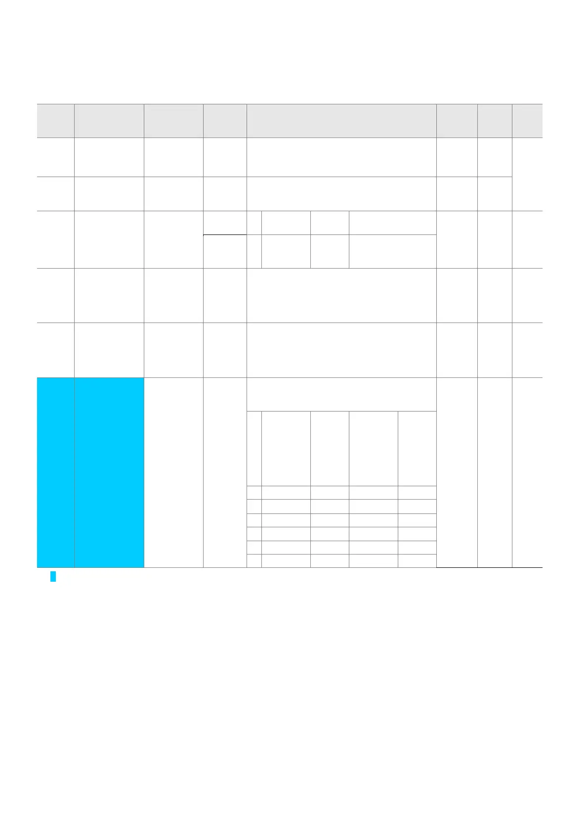
5-10
z Function group 2
LED
display
Address for
communication
Parameter
name
Min/Max
range
Description
Factory
defaults
Adj.
during
run
Page
H17 A311 [S-Curve
accel/decel
start side]
1~100
[%]
Set the speed reference value to form a
curve at the start during accel/decel. If it is
set higher, linear zone gets smaller.
40 X 7-15
H18 A312 [S-Curve
accel/decel
end side]
1~100
[%]
Set the speed reference value to form a
curve at the end during accel/decel. If it is set
higher, linear zone gets smaller.
40 X
H19 A313 [Input/output
phase loss
protection
select]
0 ~ 3 0 Disabled 1 Output phase
protection
0
O
10-4
2 Input
phase
protection
3 Input/output phase
protection
H20 A314 [Power On
Start select]
0 ~ 1 This parameter is activated when drv is set to
1 or 2 (Run/Stop via Control terminal).
Motor starts acceleration after AC power is
applied while FX or RX terminal is ON.
0 O 7-11
H21 A315 [Restart
after fault
reset
selection]
0 ~1 This parameter is activated when drv is set to
1 or 2 (Run/Stop via Control terminal).
Motor accelerates after the fault condition is
reset while the FX or RX terminal is ON.
0 O 7-11
H22
1)
[Speed
Search
Select]
0 ~ 15 This parameter is active to prevent any
possible fault when the inverter outputs its
voltage to the running motor.
0 O 8-17
1. H20-
[Power
On start]
2.
Restar
t after
instant
power
failure
3.
Operatio
n after
fault
4.
Normal
accel
Bit 3 Bit 2 Bit 1 Bit 0
0
- - - -
1 - - -
3
2- -
3
-
3- -
3 3
4-
3
- -
1)
Normal acceleration has first priority. Even though #4 is selected along with other bits, Inverter performs Speed search
#4.

 Loading...

