7-2
z Frequency setting via –10 ~ +10[V] input
Group Code Parameter Name Setting Range Initial Unit
Drive group 0.00 [Frequency Command] - 0 ~400 0.00 Hz
Frq [Frequency Mode] 2
0 ~ 8 0
I/O group I 2 [NV input minimum voltage] - 0 ~ -10 0.0 V
I 3 [Frequency corresponding to I2] - 0 ~ 400 0.00 Hz
I 4 [NV input max voltage] - 0 ~ 10 10.00 V
I 5 [Frequency corresponding to I4] - 0 ~ 400 60.00 Hz
I6 ~ I10 [V1 input]
Set Frq – [Frequency Mode] to 2.
The set frequency can be monitored in 0.00 - [Frequency Command].
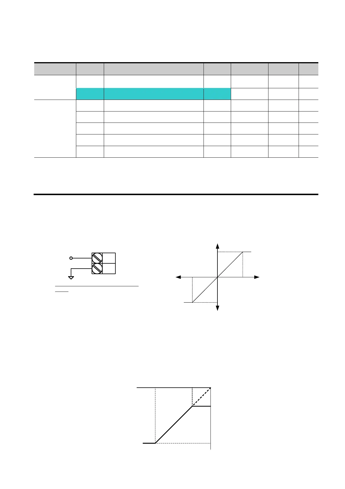
Apply –10V ~ +10V signal between V1 and CM terminal.
Output frequency corresponding to –10V ~ +10V input voltage to V1 terminal
I 2 ~ I 5: Setting input range and corresponding frequency to -10V ~ 0V V1 input voltage
Ex) when minimum (-) input voltage is -2V with corresponding frequency 10Hz and Max
voltage is –8V with run freq. 50Hz.
V1
CM
When using -10 ~ 10V from external
circuit
-10 ~ +10 V
Output freq
(Positive)
Output freq
(Negative)
Input
voltage
0~10[V]-10~0[V]
I 2I 4
I 3
I 5
Set freq.
V1 input
-8V -2V
10Hz
50Hz

 Loading...

