Chapter 4 RTD Input Module (XBF-RD04A, XBF-RD01A)
- 3 types of sensor-connecting methods are available (2, 3 and 4-wired).
- The standard wiring method for XGF-RD4A module is 3-wired wiring.
- Use an identical type of wire (thickness, length, etc.) for each 3 wire when extended lead wire is
used.
- The resistance of each conductor is to be less than 10Ω. (If larger than this, it will cause an error.)
- Resistance difference of each conductor is to be less than 1Ω. (If larger than this, it will cause an
error.)
- Length of wire is to be as short as possible and it is recommended to connect the wire directly to the
terminal block of module without connection terminal unit. If a connection terminal is to be used,
compensating wire shall be connected as shown below.
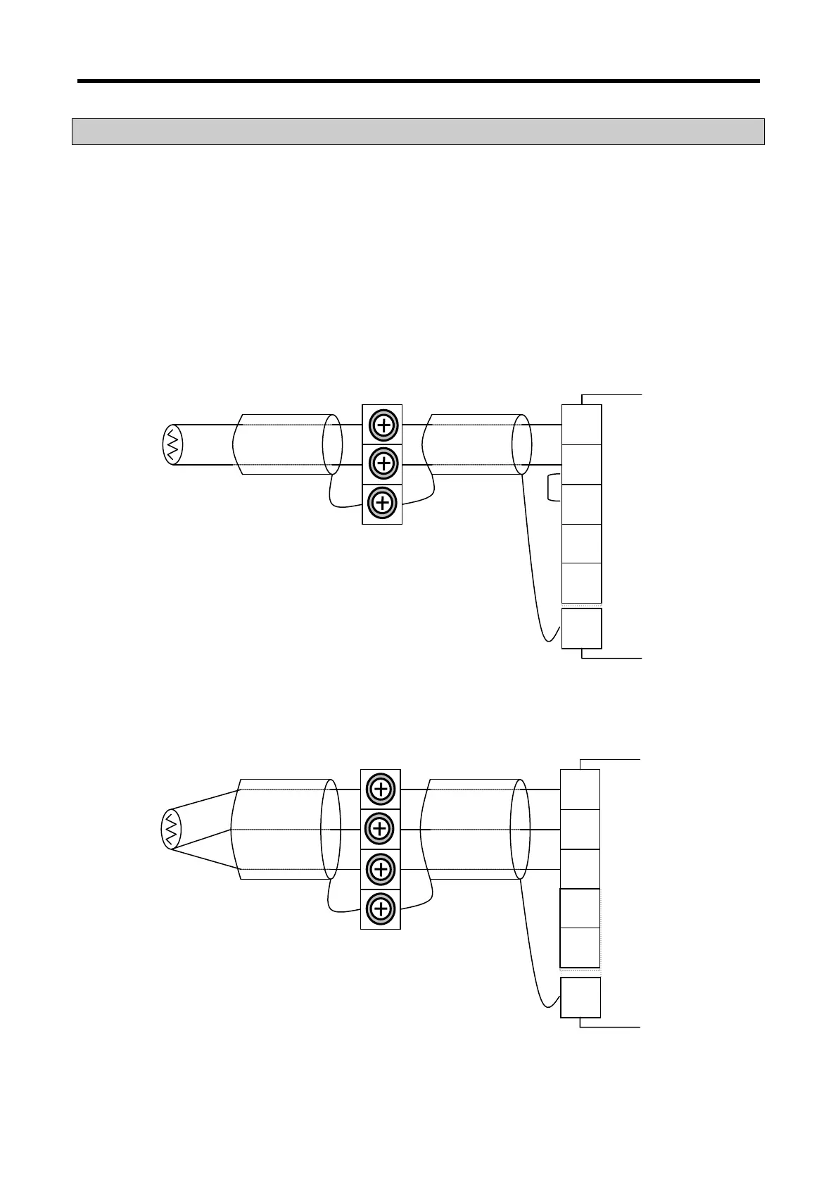
4.10.1 If 2-wired sensor is used (connection terminal unit is used)
4.10.2 If 3-wired sensor is used (connection terminal unit is used)
*1 If sensor and compensating wire are shielded,
shield line can be connected to PE terminal of
the module.
*2 Let the terminals B and b short on the terminal
block of the module if 2-wired sensor is to be
connected.
*3 DC 24V external supply terminal to supply the
analog power to module
B
PE
b
A
*1
24V
24G
*1 If sensor and compensating wire are shielded,
shield line can be connected to PE terminal of
the module.
*2 DC 24V external supply terminal to supply the
B
PE
b
A
24V
24G
4 - 9