Chapter 4 RTD Input Module (XBF-RD04A, XBF-RD01A)
4.15 Configuration and Function of Internal Memory
Here describes configuration and function of internal memory.
4.15.1 Data I/O area of RTD input module
Data I/O area of RTD input module is as shown below.
Details Content R/W
U0x.00.0
%UX0.x.0
Module ERROR flag
Module READY flag
0 Bit On(1): module error
F(15) Bit On(1): module normal
R
U0x.01.0
U0x.01.1
U0x.01.2
U0x.01.3
%UX0.x.16
%UX0.x.17
%UX0.x.18
%UX0.x.19
CH0 Run flag
CH1 Run flag
CH2 Run flag
CH3 Run flag
Bit On(1): channel run
Bit Off(0): channel stop
R
U0x.01.4
U0x.01.5
U0x.01.6
%UX0.x.20
%UX0.x.21
%UX0.x.22
CH0 Disconnection flag
CH1 Disconnection flag
CH2 Disconnection flag
Bit On(1): Disconnection
Bit Off(0): Normal
R
U0x.04 %UW0.x.4
Temperature value ×10 R
U0x.05 %UW0.x.5
−
R
U0x.06 %UW0.x.6
−
R
U0x.07 %UW0.x.7
−
R
−
−
U0x.11 %UW0.x.11 CH3 scaling value
−
R
※ In the device assigned, x stands for the slot no. on which module is installed.
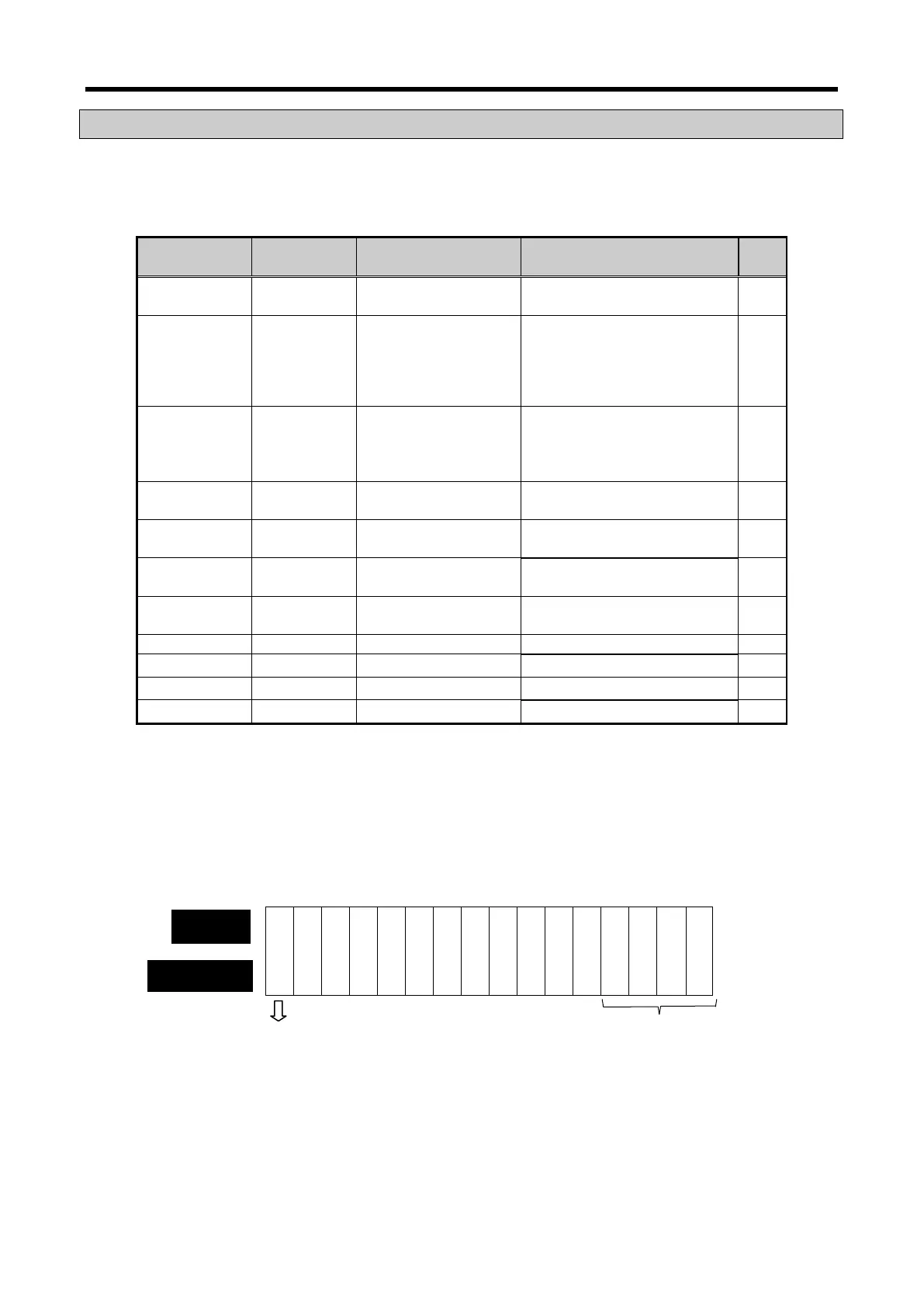
(1) Module ready/channel error information ( ( ) means device name of IEC type)
(a) U0x.00.F (%UX0.x.15): It will be ON when PLC CPU is powered or reset with A/D conversion
ready to process A/D conversion.
(b) U0x.00.0 ~ U0x.00.3 (%UW0.x.0~%UW0.x.3): It is a flag to display the error status of A/D
conversion module.
Ready
— — — — — — — — — — — — — —
Bit On (1): error, Bit Off (0): normal
Bit On (1): normal, Bit Off (0): error
4 - 21
 Loading...