Chapter 3 Analog Output Module (XBF-DV04A, XBF-DC04A, XBF-DC04B)
3 - 9
3.8.1 Precautions for wiring
(1) Use separate cable of an A.C. power line and an external output signal of an analog output
module to prevent a surge or inductive noise from the A.C. side.
(2) Select the cable with consideration of an ambient temperature and a permitted current limit. It is
recommended over AWG22 (0.3㎟).
(3) Don’t let the cable at close range to hot devices or materials. And don’t bring it into contact with
oil for a long time. These are the factors of a short circuit occurs unusual operation or damages
devices.
(4) Check the polarity before external power is supplied to the terminal.
(5) It may produce inductive hindrance that is a cause of unusual operations or defects if you wire
the cable with a high-voltage line or a power line.
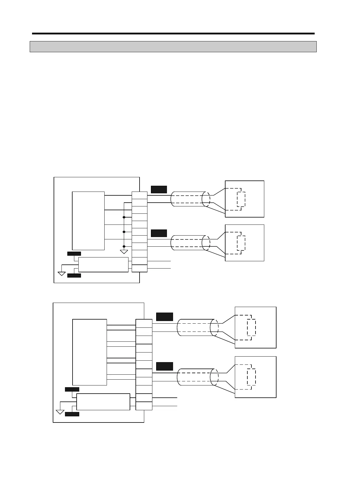
3.8.2 Wiring example
(1) Wiring example for analog voltage output module
(2) Wiring example for analog current output module
※ 1: Use a 2-core twisted shielded wire.
※ 2: The (-) terminals of the channel should be separated from each other. It may cause
malfunction.
D/A
Conversion
circuit
DC/DC
Conversion circuit
CH0+
CH0-
CH3+
CH3-
CH1+
CH1-
CH2+
CH2-
DC +24V
DC 0V
CH0
CH3
+15V
-15V
DC +24V
DC 0V
Over 2kΩ
Over 2kΩ
Motor driver etc.
Motor driver etc.
GND
GND
XBF-DV04A
※1
※1
D/A
Conversion
circuit
DC/DC
Conversion circuit
CH0+
CH0-
CH3+
CH3-
CH1+
CH1-
CH2+
CH2-
DC +24V
DC 0V
CH0
CH3
+15V
-15V
DC +24V
DC 0V
Under
510Ω
Under
510Ω
Motor driver etc.
Motor driver etc.
GND
GND
XBF-DC04A
※1
※1
※2
※2