Lucent Technologies Lineage
®
2000 50A -48V 364A-3 SR Series Rectifier
5 - 10 Installation Issue 6 January 1997
Initial Power-up
and Adjustment
Set the ac supply and rectifier controls as follows:
Associated ac circuit breaker ON or replace fuse at the ac service
panel.
Rectifier POWER switch to STBY and DC OUTPUT circuit
breaker lever to OFF.
1. Ensure the controller is set so that the rectifier will be
enabled and in float mode (refer to controller manual if
necessary). If no controller exists, the rectifier will default
to float mode.
2. Verify that only the following LEDs are lit on the rectifier:
POWER STBY, CB OFF.
3. At the rectifier, set the POWER switch to ON. Verify that
only the following LEDs are lit: POWER ON, CB OFF.
Check that OUTPUT CURRENT display reads 00.0.
4. Connect DMM to the PLANT (+) and (-) test jacks on the
rectifier. If batteries are present or if other rectifiers in the
plant are ON and adjusted properly, the meter should read
the proper plant voltage. If there are no batteries or other
rectifiers ON, the meter should read zero.
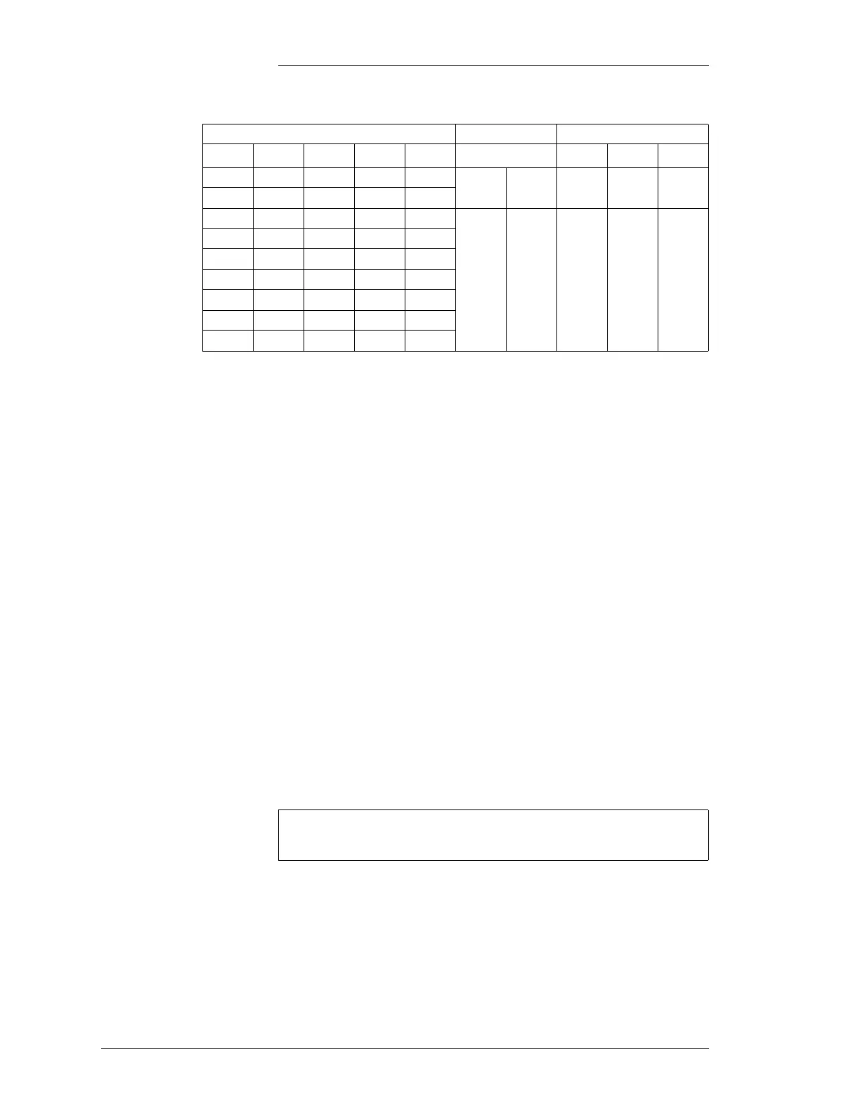
Table 5-B: 364A3 Rectifier Dip Switch (701) Settings
Internal Selected HVSD (Volts) Load Share Back-Up HVSD
Volts1234 5 Volts67
50.0 1111
enabled disabled
51.0 1110
52.0 1101
10
54.5
57.0
59.5
1
1
0
1
0
0
53.0 1100
54.0 1011
55.0 1010
56.0 1001
57.0 1000
58.0 0111
Note
If LED’s status is not as specified, refer to Section 7,
Maintenance, for troubleshooting help.