ODK4 QUICK REFERENCE GUIDE
Luminator Technology Group
1
SECTION 1
ODK4 DESCRIPTION
1.1 ODK Connectivity
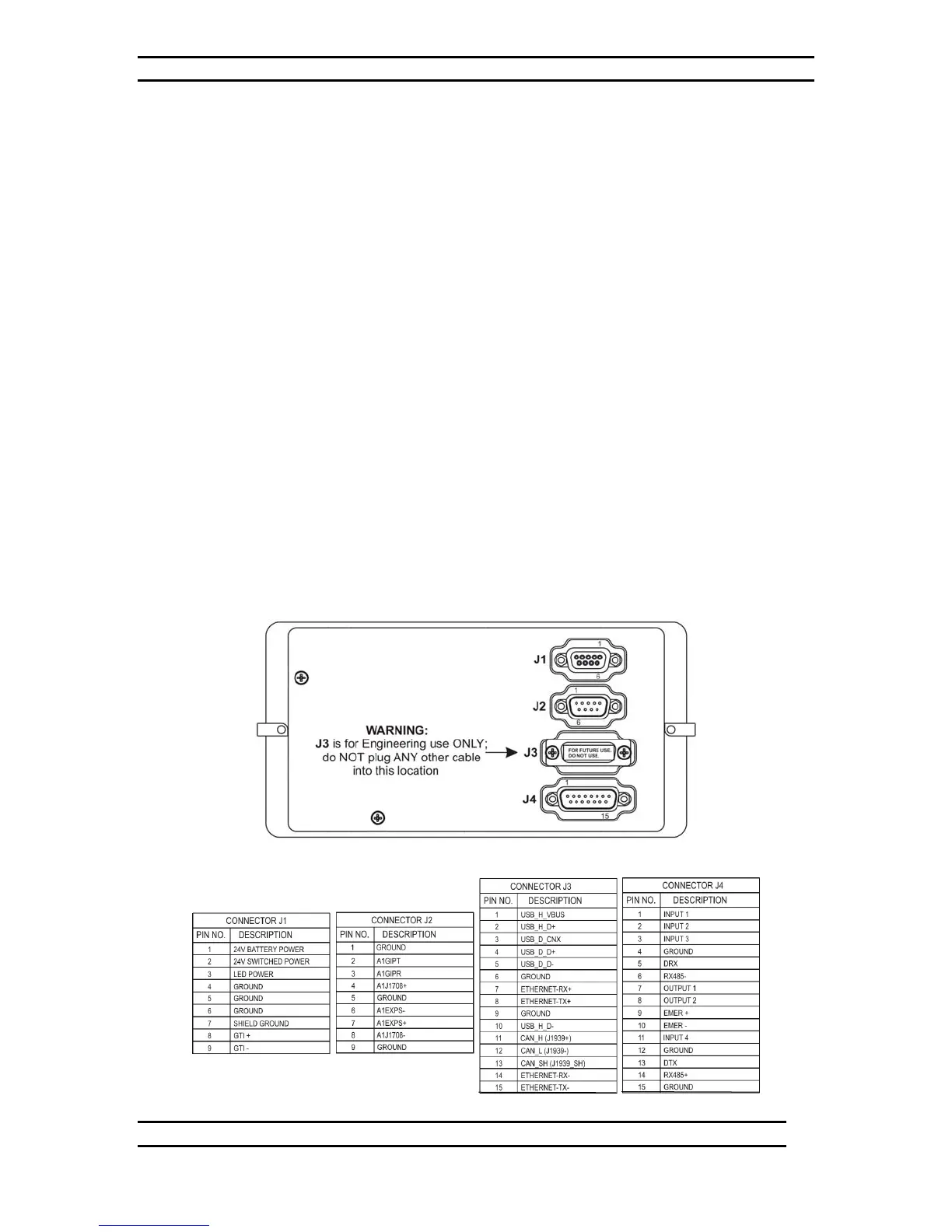
The ODK4 is equipped with two DB-9 and two DB-15 connectors located on the back of
the ODK (see Figure 1-1):
• J1 is a 9 pin female Dsub connector and provides the sign data interface;
24V battery power; 24V switched power; and LED power
• J2 is a 9 pin male Dsub connector and provides one channel for RS485
signals; one channel for J1708; and a one channel RS232 interface (Tx
and Rx only)
• J3 is a 15 pin female Dsub connector and provides one channel for
J1939; one channel for Ethernet; one channel for a USB host; and one
channel for a USB device
WARNING:
Connector J3 is for future use and is not used in this system
• J4 is a 15 pin male Dsub connector and provides for an emergency
switch interface; one RS485 interface for Luminator’s Quantum Lighting
control, one RS232 channel for ODK4 debugging, and four input/two
output interfaces
Figure 1-1. ODK4 Connectors
510632-004