User Manual CANopen/EtherCAT
18
3.4 Display of operating states via 7-segment display
D1 D2 Meaning Parameter
System states
8. 8.
Device in reset state
0.
Auto-initialization on device startup (Start)
S.*
)
1.
1) Not ready to switch on (no DC-link voltage) (NotReadyToSwitchOn)
S.*
)
2.
1) Switch-on inhibit (DC-link is OK,
power stage not ready)
(SwitchOnDisabled)
3.
Ready to switch on (power stage is ready) (ReadyToSwitchOn)
4.
On (power is connected to the device)2) (SwitchedOn)
5.
Drive ready (current applied to drive and ready
for reference input) 2)
(OperationEnable)
6.
Emergency stop 2) (QuickStopActive)
7.
Fault response active 2) (FaultReactionActive)
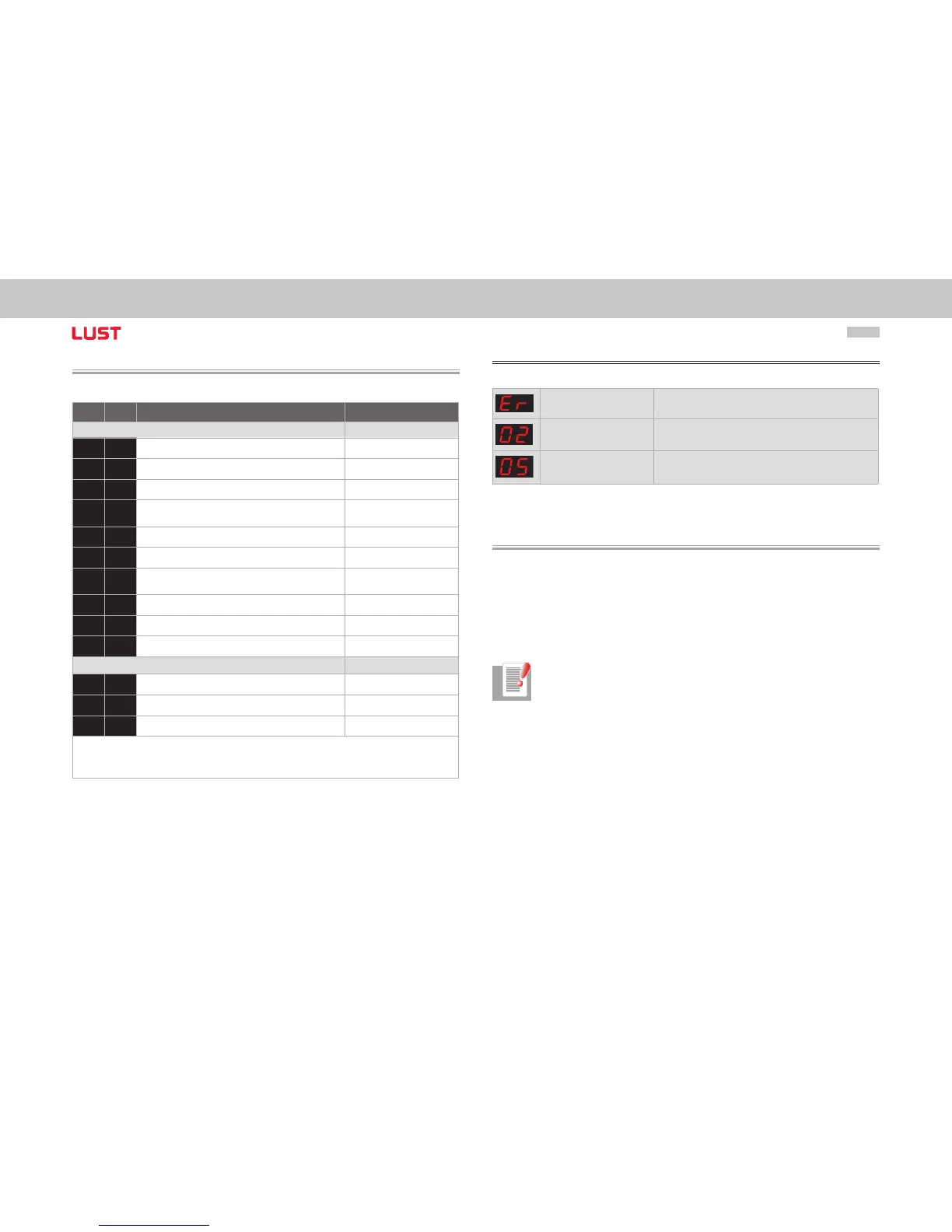
E R
Fault (see below) (Fault)
Appears in the event of error
E R.
Display for errors or non-acknowledgeable errors
X X
Error number (decimal)
Y Y
Error localization (decimal)
1) S. flashes, if the function STO (Safe Torque Off) is active, the display is not lit if the function is not active.
*) It does not involve a “safe display“ under the terms of EN 61800-5-2.
2) The point flashes if the power stage is active.
Example of the flash sequence:
ER > 02 > 05 * ER > 02 > 05 ...
Error: ER = “Fault“
Error name: 02 = “Error in the parameter list“
Description of error: 05 = “Function for checking current parameter list“
3.5 Hardware enable
ServoOne has a control input for ENPO hardware enable on the control terminal.
This input must be configured to operate the power stage at 24 V.
The device also provides the function “STO (Safe Torque Off)“ (see Operation Manual or
Application Manual ServoOne), category 3, control terminal ISDSH. For these devices the
relevant function logic must be implemented by way of the higher-order controller as
per the Application Manual.
Note: Without configuration of the inputs ENPO and ISDSH the device stays
in state 1 = “Not Ready to Switch On“ or 2 = “Switch On Disabled“.
Only after correct configuration can the state be exited by a “Shutdown“
command via bus.
➢