EasyManua.ls Logo

Lust ServoOne - Mounting and Connection of Canopen; Setting the Address

Lust ServoOne
74 pages
Print Icon
To Next Page IconTo Next Page
To Previous Page IconTo Previous Page
Loading...
User Manual CANopen/EtherCAT
9
[Chapter 2]
2 Mounting and Connection
of CANopen
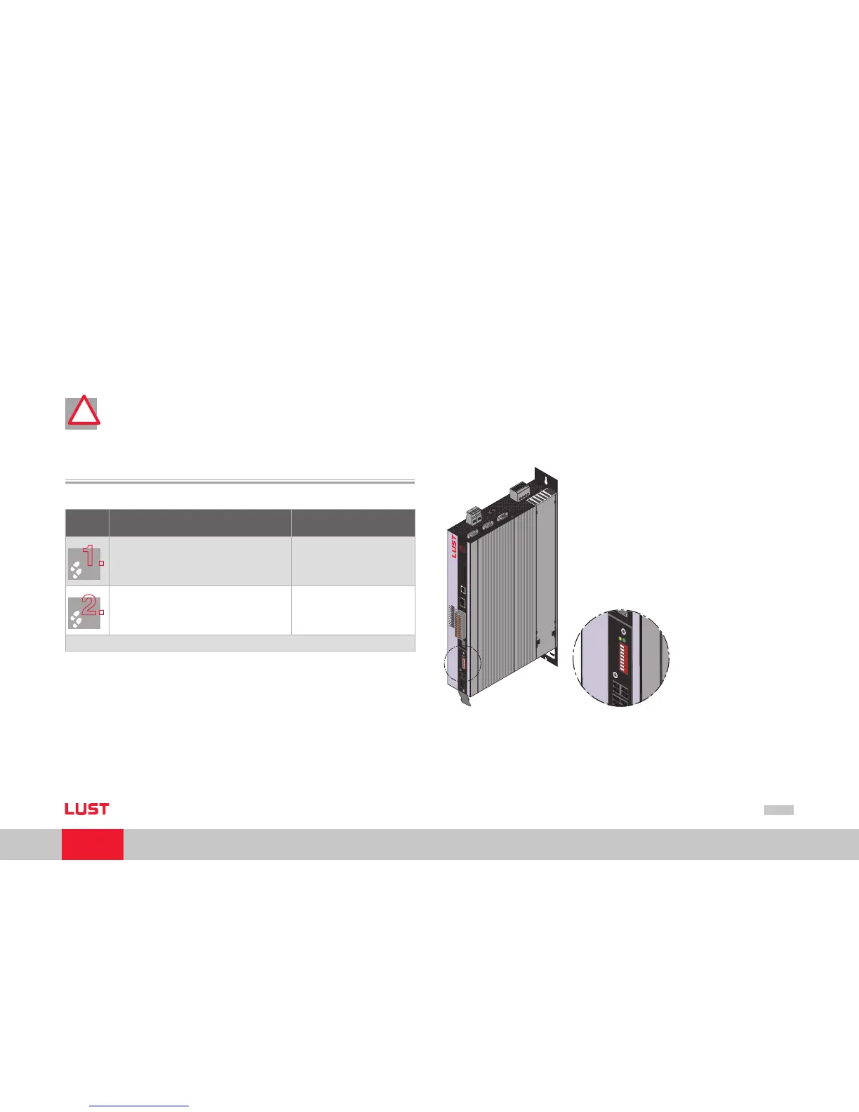
Attention: Do NOT insert or remove the CANopenconnector during opera-
tion.
2.1 Setting the address
Step Action Note
1.
Find out which address is assigned to
the module you are installing.
Ask your project engineer.
2.
Select the mode of addressing:
by bus address parameter
by DIP switch (S4)
by bus address parameter and DIP switch (S4)
See below
Address setting finished; for further procedure see Installation.
!!
Three possible methods of address assignment
Only using bus address parameter 2005-COM_CAN_Adr: You will find parameter
2005-COM_CAN_Adr (factory setting 1) in the “field bus“ subject area under
CANopen.
Only using DIP switch S4
Combination of bus address parameter and DIP switch S4
CAN address = hardware address (S4) + Parameter 2005-COM_CAN_Adr
This option is advantageous, for example, if you intend always to use the same
parameter set with up to 15 drives, but the lowest address is 30. Parameter
2005-COM_CAN_Adr is then set to 30. The device address is then defined using
the coding switch, which ranges from 0-15.
T
y
p
e
:
In
:
O
u
t
:
3
5
6
3
3
L
a
h
n
a
u
w
w
w
.
l
u
s
t
-
t
e
c
.
d
e
M
a
d
e
in
G
e
r
m
a
n
y
U
S
C
L
IS
T
E
D
I
n
d
.
C
o
n
t.
E
q
.
1
9
B
B
SN.
:
S
O
A
8
4
.
0
0
6
.
0
0
0
0
.
0
0
0
0
.
0
24
23
22
21
20
19
18
17
16
15
14
13
12
11
10
9
8
7
6
5
4
3
2
1
REL
REL
ISDS
H
IS
D
06
IS
D
05
IS
D
04
ISD03
IS
D
02
IS
D
01
ISD00
+
24
V
D
GN
D
RS
H
RS
H
EN
P
O
OSD0
2
OSD0
1
OSD0
0
ISA1
-
ISA1
+
ISA0
-
ISA0
+
+2
4
V
DGND
A
C
H
T
U
N
G
W
A
R
N
I
N
G
K
o
n
d
e
n
s
a
t
o
r
e
n
e
n
t
-
l
a
d
e
z
e
i
t
>
3
m
i
n
.
B
e
t
r
i
e
b
s
a
n
l
e
i
t
u
n
g
b
e
a
c
h
t
e
n
!
C
a
p
a
c
i
t
o
r
d
i
s
c
h
a
r
g
e
t
i
m
e
>
3
m
i
n
.
P
a
y
a
t
t
e
n
t
i
o
n
t
o
th
e
o
p
e
r
a
t
i
o
n
m
a
n
u
a
l
!
o
n
e
S
e
r
v
o
5
6
x
3
x
1
x
2
x
4
x
5
x
1
0
x
9
x
6
x
7
x
8
x
1
1
L
1
L
2
L
3
ϑ
-
ϑ
+
ϑ-
ϑ+
ϑ
-
ϑ
+
ϑ-
ϑ+
1 2 3 4 5 6 7 8
x
3
2
s
4
x
3
3
h
14
h
15
AC
H
TUNG
WA
R
NING
K
on
d
ens
a
tore
nen
t-
lad
e
z
eit
>
3
m
in.
B
etriebsa
nle
itu
n
g
bea
c
hten
!
C
ap
a
cit
o
r disc
harg
e
ti
m
e
>
3
m
i
Pa
y
a
tt
en
t
io
ope
r
1 2 3 4 5 6 7 8
s
4
x
33
h
14
h
15
Figure Position of CAN connection on ServoOne
1.
2.
3.

Table of Contents

Related product manuals