User Manual CANopen/EtherCAT
11
[Chapter 2]
The LEDs have the following function:
LED Function Meaning
H14 (yellow LED)
CANopen
network state
The LED displays the current network state.
NMT STOPPED
ð flashing with 800 ms cycle
NMT PRE-OPERATIONAL
ð flashing with 1600 ms cycle
NMT OPERATIONAL
ð permanently lit.
•
•
•
H15 (green LED)
Voltage supply CAN
option
Permanently lit, if the 24V supply of the option
from CAN bus applies.
Table Meanings of LEDs
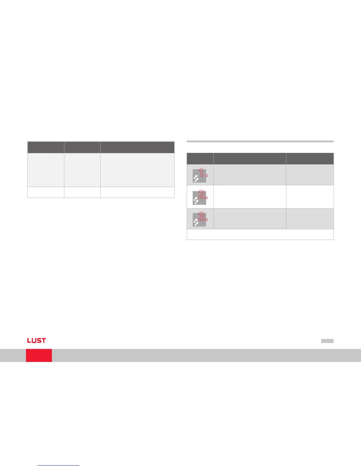
2.3 Installation
Step Action Note
Make sure the hardware enable is wired on
ServoOne (X4).
see Operation Manual
Wire the CAN connection using connector X32
Connection of CAN signal cables
Connection of interface power supply
Activation of the internal bus terminating
resistor on the final drive controller
•
•
•
see Specification of CAN bus
connection table and Assign-
ment of connection X19 table
Switch on the drive device.
Electrical installation is finished; for how to proceed further, refer to section 4
“Commissioning and configuration“.
The CANopen interface is integrated in ServoOne. The connection is made via connec-
tor X32. The interface is isolated from the drive controller electronics. The supply to the
isolated secondary side is provided by the customer via connector X32.