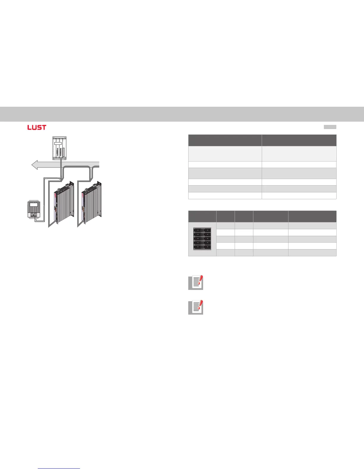
Figure System connection
Connection Spring-type terminal
Wave terminating resistance
- Bus termination -
120 W (internal)
Activation of the bus termination in the device
via switch 8 in the CAN option
Max. Input frequency 1 MHz
Ext. voltage supply
+24 V +25 %, 50 mA
(isolated from drive controller)
Voltage ripple Max. 3 Vss
Current consumption Max. 50 mA per user
Cable type 4-wire, surge impedance 120 W
Table Specification of CAN bus connection
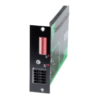
Terminal X32 PIN PIN Function Description
10 5 CAN_+24V external 24V supply
9 4 CAN_H CAN High
8 3 CAN_SHLD CAN Shield (optional)
7 2 CAN_L CAN Low
6 1 CAN_GND CAN Ground (0V)
Table Assignment of connection X19
Note: Both connectors of terminal X32 are connected to each other in the
device.
Note: The external 24 V supply for the option board is essential. It is not sup-
plied by the device.