User Manual CANopen/EtherCAT
13
[Chapter 2]
2.3 Transmission speeds
The CAN bus can be operated at the following Baud rates:
Transmission
speed
Maximum line length across
the complete network 1)
1000 kBaud 25 m Factory setting
500 KBaud 100 m
250 kBaud 2) 250 m
125 kBaud 2) 500 m
50 kBaud 3)
1000 m
25 kBaud 3)
2500 m
1) Rounded bus length estimation (worst case) on basis 5 ns/m
propagation delay and a total effective device internal in-out
delay as follows:
1M-800 kbit/s: 210 ns
500 - 250 kbit/s: 300 ns (includes 2 * 40 ns for optocouplers)
125 kbit/s: 450 ns (includes 2 * 100 ns for optocouplers)
50 -10 kbit/s: Effective delay = delay recessive to dominant plus
dominant to recessive divided by two.
2) For bus length greater than about 200 m the use of optocouplers is recommended. If optocouplers are
placed between CAN Controller and transceiver this affects the maximum bus length depending upon
the propagation delay of the optocouplers i.e. -4m per 10 ns propagation delay of employed optocoup
-
ler type.
3) For bus length greater than about 1 km bridge or repeater devices may be needed.
Table Transmission speeds
When selecting the transmission rate it should, however, be ensured that the line length
does not exceed the permissible line length for the transmission rate in question.
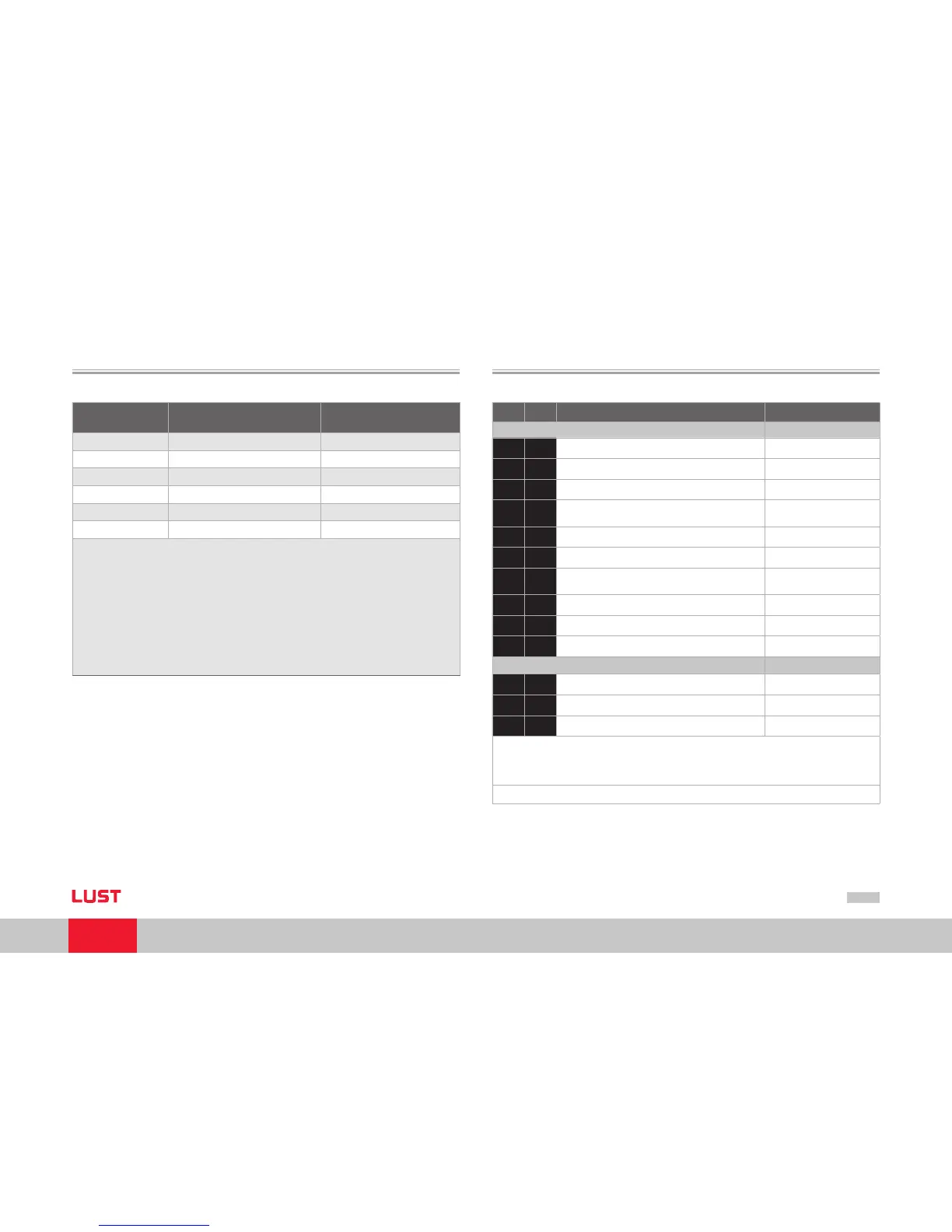
2.4 Display of the operating states via 7-segment display
D1 D2 Meaning Parameter
System states
8. 8.
Device in reset state
0.
Auto-initialisation on device startup (Start)
S.*
)
1.
1) Not ready to switch on (no DC-link voltage) (NotReadyToSwitchOn)
S.*
)
2.
1) Switch-on inhibit (DC-link is OK, power stage
not ready)
(SwitchOnDisabled)
3.
Ready to switch on (power stage is ready) (ReadyToSwitchOn)
4.
On (power is connected to the device)2) (SwitchedOn)
5.
Drive ready (current applied to drive and drive
ready for reference input) 2)
(OperationEnable)
6.
Quick stop 2) (QuickStopActive)
7.
Fault response active 2) (FaultReactionActive)
E R
Fault (see below) (Fault)
Displayed in the event of a fault
E R.
Display for errors or non-acknowledgeable errors
X X
Error number (decimal)
Y Y
Error localization (decimal)
1) S. flashes, if the function STO (Safe Torque Off) is active, the display is not lit if the function is not
active.
*) It does not involve a “safe display“ under the terms of EN 61800-5-2.
2) The point flashes if the power stage is active.