214633 24 Revision C
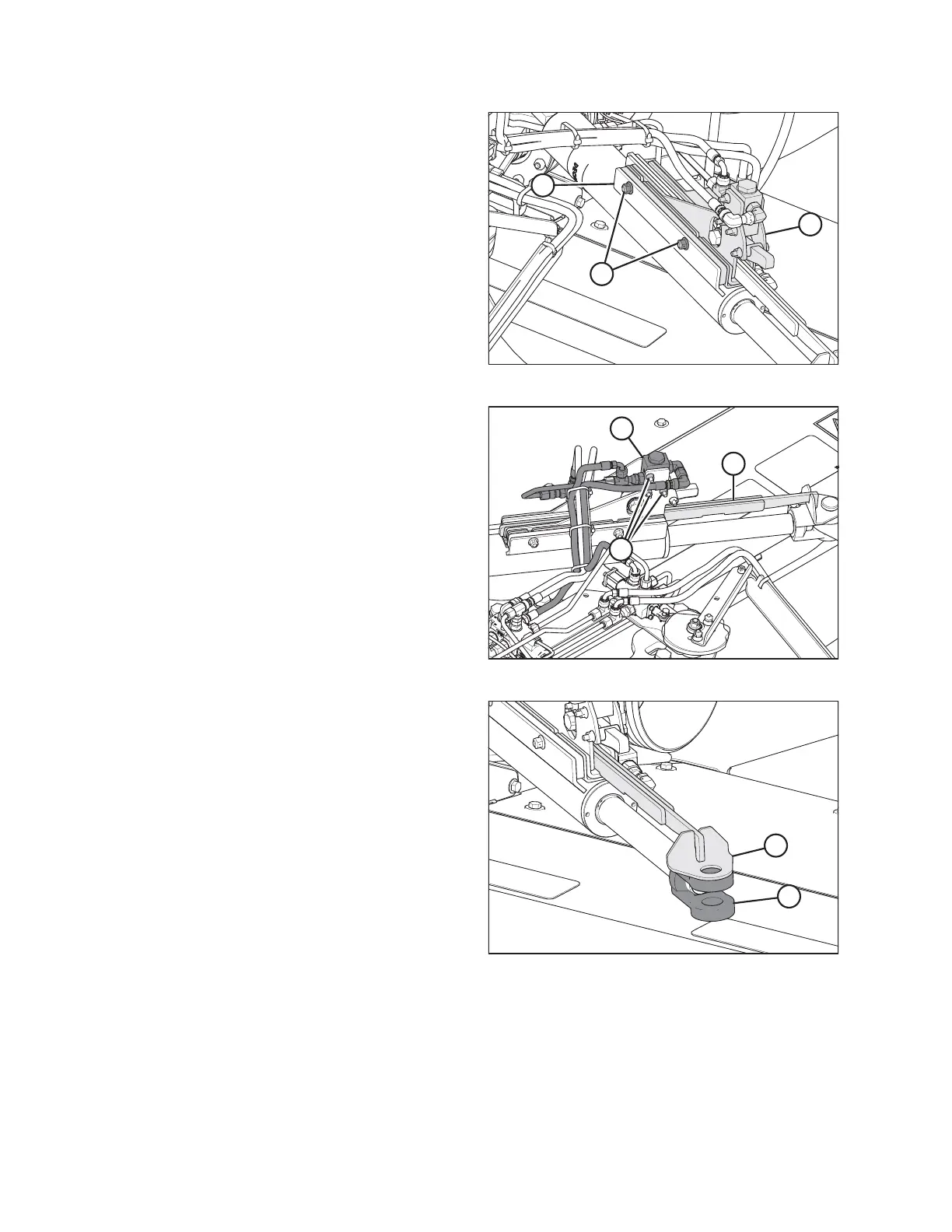
Figure 3.32: Alignment Control – Rear Right View
3. Secure cam assembly (A) onto hitch swing cylinder plate (B)
with bolts and nuts (C). Torque nuts (C) to 55–60 Nm
(40–45 lbf·ft).
NOTE:
When installing cam assembly (A), check for hose twisting.
If required, loosen hose fitting to allow hose to untwist.
Torque fitting when complete.
Figure 3.33: Alignment Control – Rear Right View
4. Check travel of cam arm (A) by sliding it in and out of cam
assembly (B).
NOTE:
If the cam arm does NOT slide easily, loosen valve
mounting bolts (C) and position valve (B) at the top of the
mounting holes. Retighten valve mounting bolts (C).
Figure 3.34: Alignment Control – Rear Right View
5. Align hole in cam arm (A) with hole in clevis (B) on the rod
end of the cylinder.
INSTALLATION INSTRUCTIONS