214633 23 Revision C
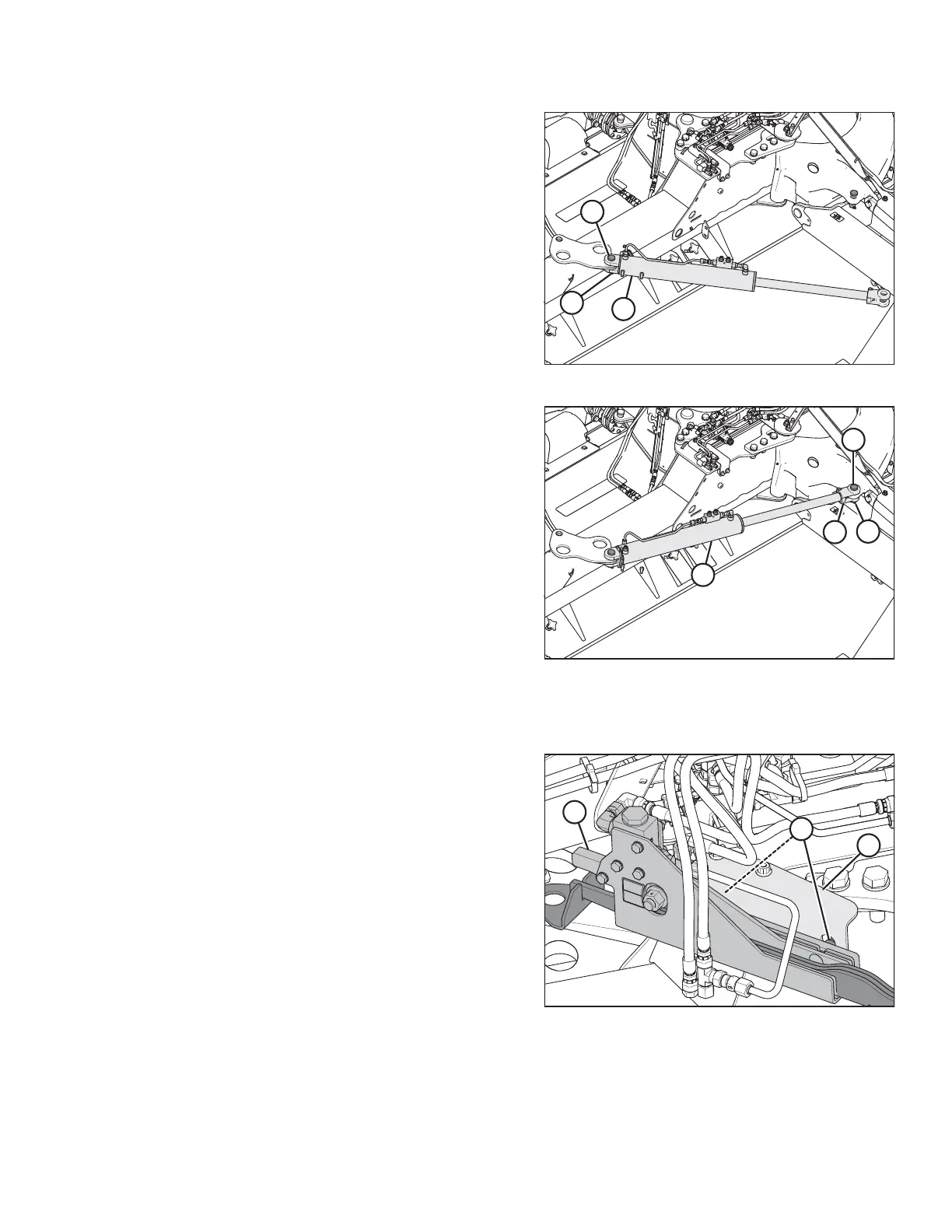
Figure 3.29: Transport Swing Cylinder
5. Install barrel end of transport swing cylinder (A) onto the
carrier frame with clevis pin (B) (MD # 281101). Secure
clevis pin with cotter pin (C) (MD #18609).
Figure 3.30: Swing Cylinder – Rear Left View
6. Connect rod end (B) of transport swing cylinder (A) to
transport casting. Align holes and install clevis pin (C)
(MD # 281101). Secure with cotter pin (D) (MD #18609).
3.2.6 Installing Transport Alignment Control
Figure 3.31: Alignment Controls – Front Right View
1. Remove cam assembly (A) from shipping support (B).
2. Remove nuts (C) from the cam assembly.
INSTALLATION INSTRUCTIONS