214633 45 Revision C
Chapter 4: Checking and Adjusting the Cam on the Transport
Deploy / Swing Mechanism
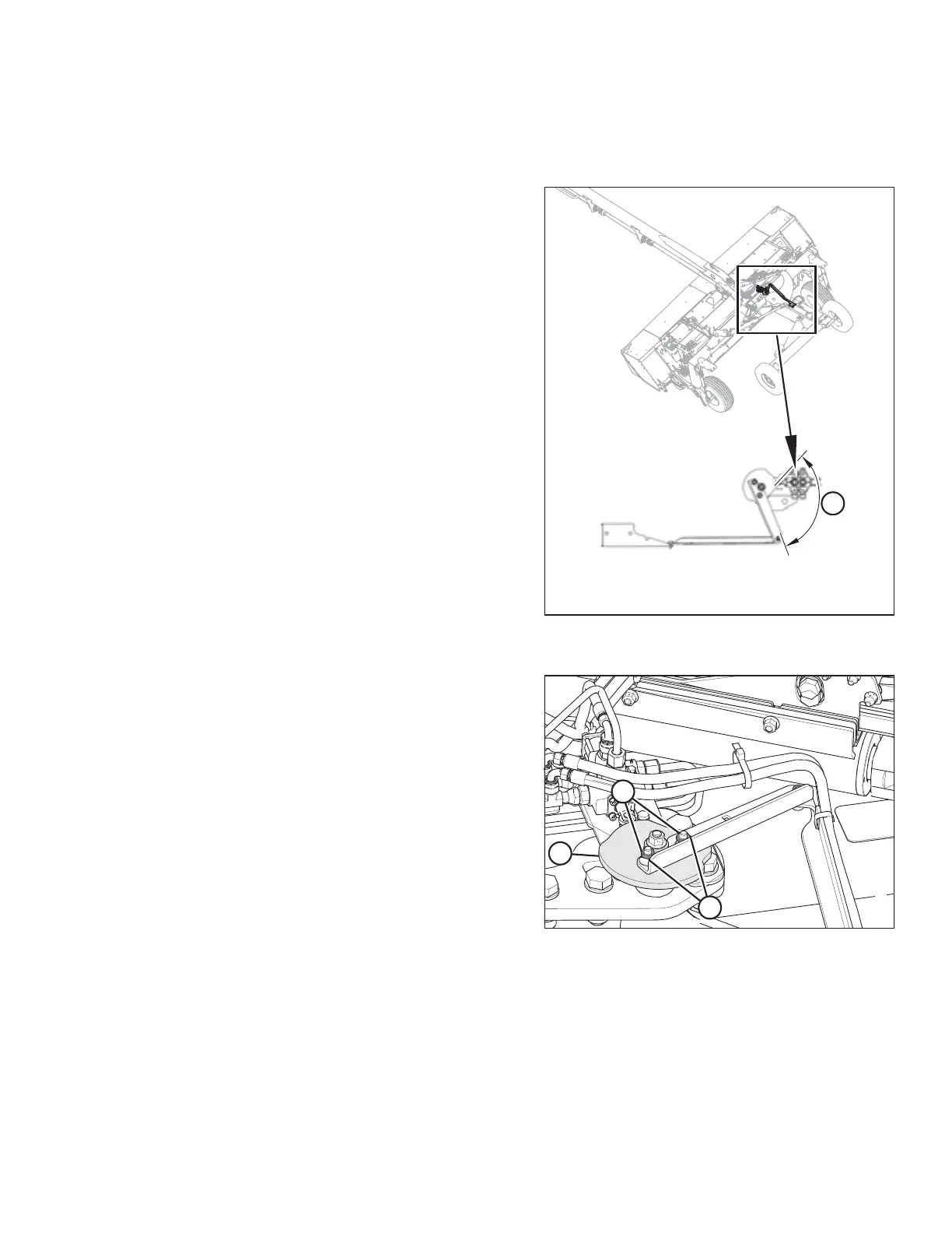
Figure 4.1: Transport Deploy / Swing Mechanism
Assembly
Cam angle (A) on the transport deploy/swing mechanism
assembly is factory-set to 112°. It may be necessary to adjust
the cam angle if the transport does NOT properly deploy. When
the system is functioning properly, the header should start to
rotate as the transport wheels reach the end of their travel
(beneath the header).
Figure 4.2: Transport Deploy / Swing Mechanism
Assembly
1. Loosen two M10 jam nuts (A), two M10 hex flange nuts (B),
and rotate cam plate (C) to achieve the proper angle.
Reposition cam as follows:
• Rotate COUNTERCLOCKWISE if the transport tires
deploy too close to the header tires, before the
transport wheels are fully under the header.
• Rotate CLOCKWISE if the tires go underneath
the header, but the header does not begin to rotate.
2. Tighten two M10 hex flange nuts (B) and two M10 jam
nuts (A).
3. To test the transport deploy/swing mechanism, refer to:
• 5.5 Converting from Transport to Field Mode – With
Road-Friendly Transport
™
, page 56
• 5.4 Converting from Field to Transport Mode – With
Road-Friendly Transport
™
, page 51