214633 32 Revision C
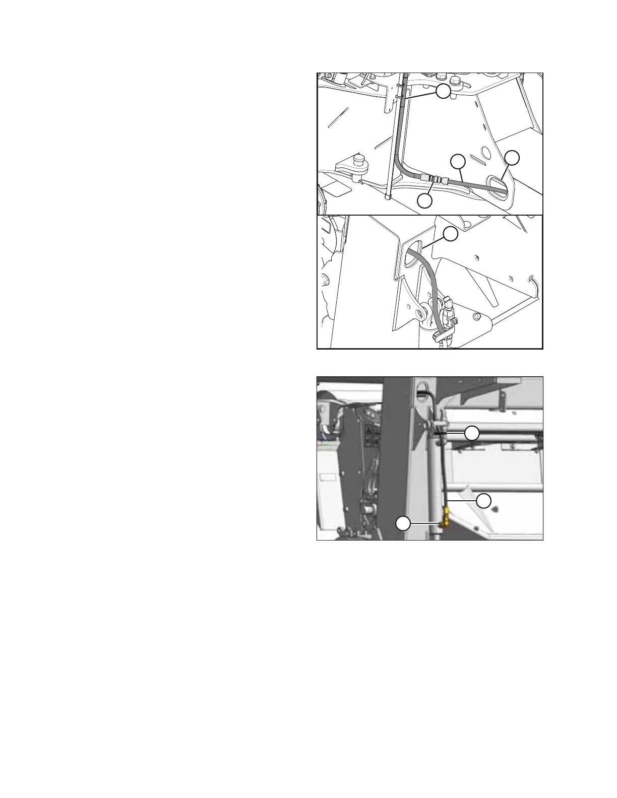
Figure 3.49: Lift Hose
28. Route hose (A) (MD #247106) through opening (E) at the
rear of the frame.
29. Feed shortest hose (A) through opening (B) in the carrier
frame as shown with male end (C) at the hitch pivot.
30. Connect hose (A) (MD #247106) and hose (D) (MD #224160
or MD #224162) at the hitch pivot.
Figure 3.50: Lift Cylinder
31. Retrieve ORFS-6 x ORB-8 elbow (MD #136149) from the
hardware bag.
32. Remove the plug at the base of the lift cylinder and install
elbow (A) as shown.
33. Connect hose (B) to elbow (A) and tighten.
34. Tighten the remaining connections.
35. Secure hose (B) to the cylinder with a cable tie (C)
(MD #30753).
INSTALLATION INSTRUCTIONS