214633 48 Revision C
Figure 5.1: Hydraulic Connection
3. Connect the hitch swing cylinder hoses (collars with #2) to
tractor’s hydraulic circuit (A). For instructions, refer to 3.6
Connecting Hydraulics, page 41.
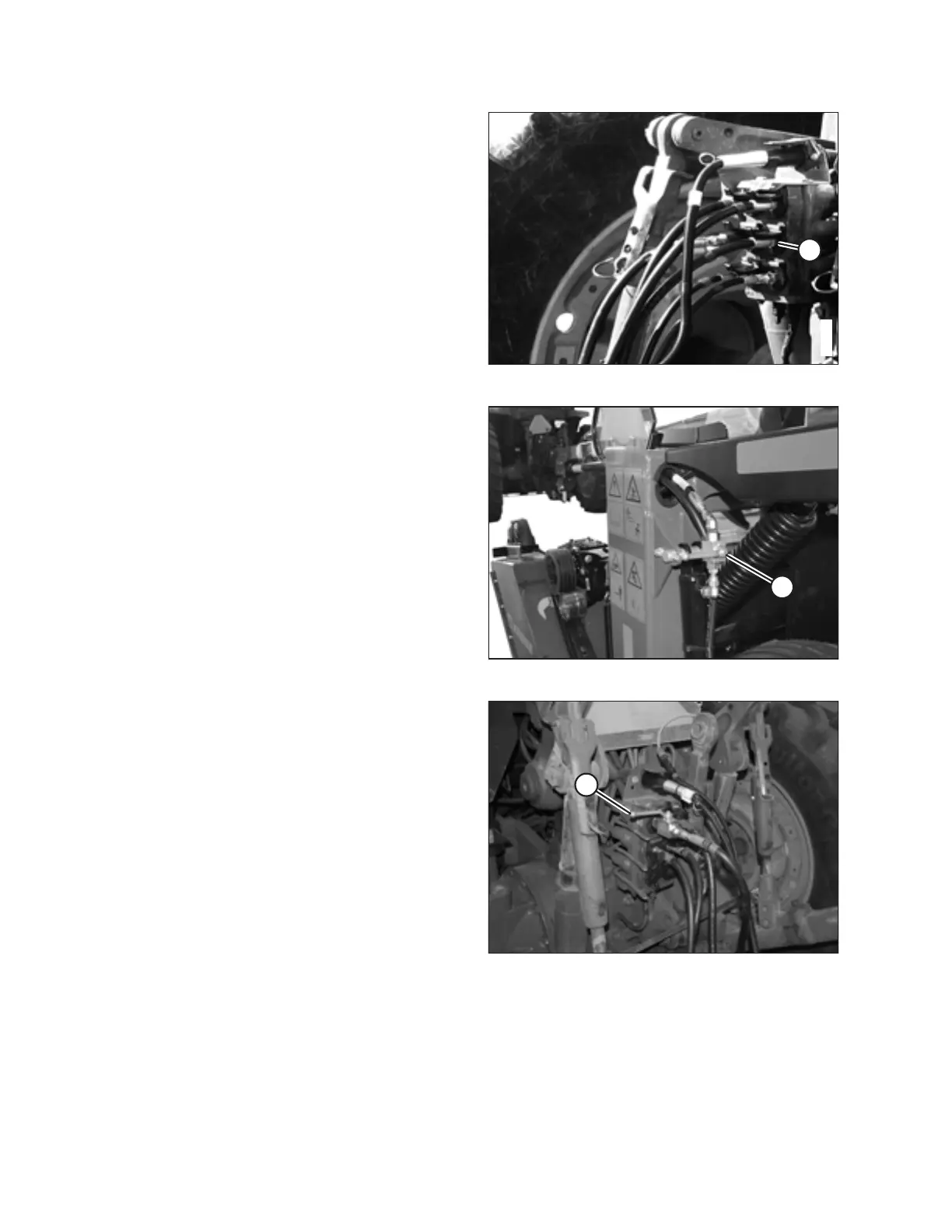
Figure 5.2: Cylinder Lock-Out Valve
4. Raise the rotary disc pull-type fully and close the lift
cylinder lock-out valve by turning handle (A) to the closed
position (90° to the hose). Repeat on the opposite side.
5. Swing the rotary disc pull-type completely to the left, then
completely to the right. Repeat three or four times to
charge the hitch swing circuit.
6. Swing the rotary disc pull-type so that it is centered behind
the tractor.
Figure 5.3: Hitch Swing Lock-Out Valve Shown in
Closed Position
7. Close the hitch swing lock-out valve by turning handle (A)
to the closed position (90° angle to the hose).
8. Ensure tires are properly inflated.
9. Ensure the slow moving vehicle (SMV) sign, reflectors, and
lights are clean and visible at rear of rotary disc pull-type.
10. Refer to 5.2 Transporting with a Tractor, page 49 for
transport instructions.
TRANSPORTING THE ROTARY DISC PULL-TYPE