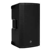
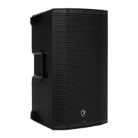
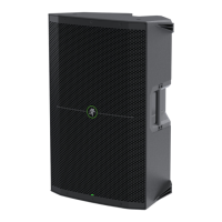
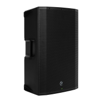
THUMP210XT 10" 1400W ENHANCED COMPACT POWERED LOUDSPEAKER
8
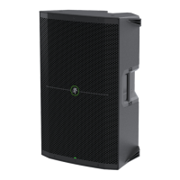
Chapter 2 : Thump20XT Rear Panel Features
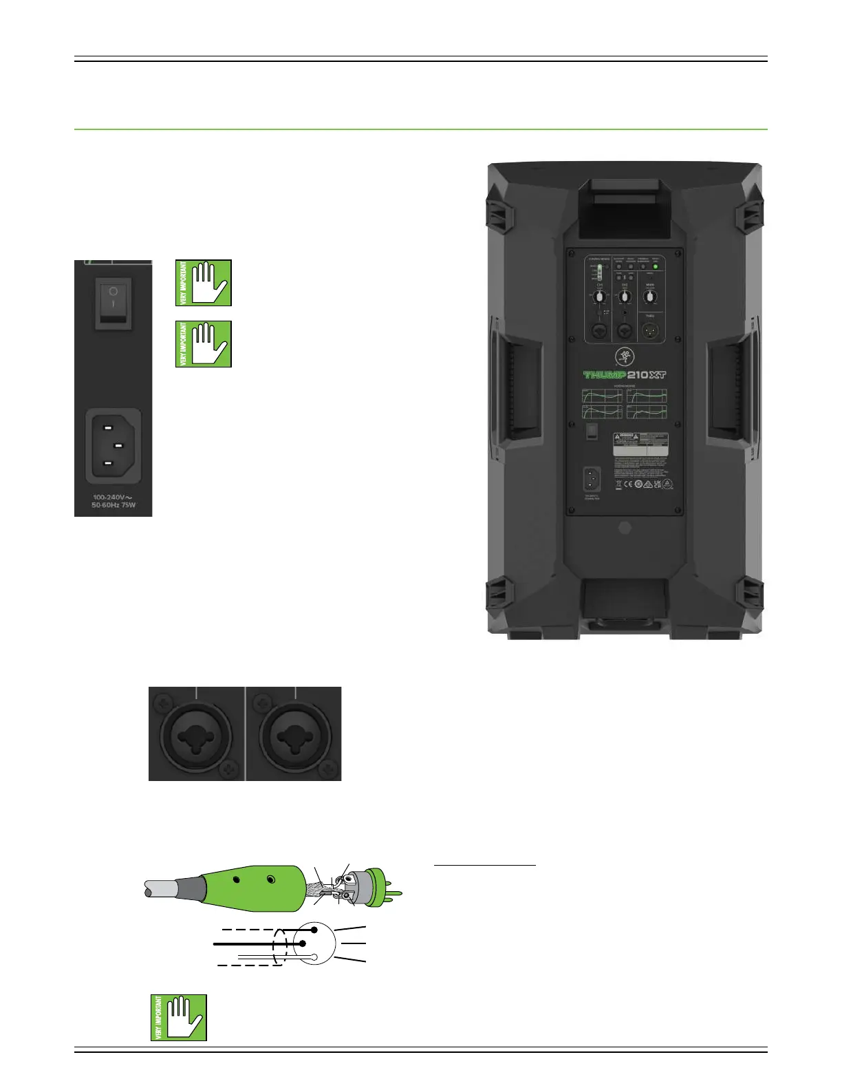
Power Connector
This is a standard 3-prong IEC power connector. Connect
the detachable power cord (included in the packaging with
the loudspeaker) to the power receptacle, and plug the other
end of the power cord into an AC outlet.
Make sure that the AC power is matched
to the AC power indicated on the rear panel
(near the IEC receptacle).
Warning: Disconnecting the plug’s ground
pin is dangerous. Don’t do it!
Power Switch
Press the top side of this rocker switch inwards to turn
on the loudspeaker. Press the bottom side of this rocker
switch inwards to turn o the loudspeaker.
As a general guide, the mixer (or other signal source) should
be turned on first, subwoofers next, and loudspeakers last.
As such, the loudspeakers should also be turned o first,
followed by the subwoofers, then the mixer. This will reduce
the possibility of any turn-on or turn-o thumps and other
noises generated by any upstream equipment from coming
out of the speakers.
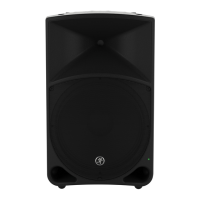
XLR and /4" Combo Input Jacks
Input channels and 2 may accept a balanced mic signal using an XLR connector.
They are wired as follows, according to standards specified by the AES (Audio Engineering Society).
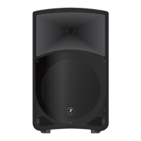
XLR Balanced Wiring:
Pin = Shield (ground)
Pin 2 = Positive (+ or hot)
Pin 3 = Negative (– or cold)
NEVER connect the output of an amplifier directly to a Thump20XT’s input jack.
This could damage the input circuitry and we wouldn’t want that now, would we?
3
1
SHIELD
COLD
HOT
SHIELD
COLD
HOT
3
2
1