If you want to connect shortly two wires by (-) signal.
E.g.: Mostly used for installing alarm gas relays.
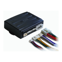
IV. WIRING ARRANGEMENT
1 – white – Accessory Output
- connect to the switchboard (to the +12V wire) with the key in the ACC position. If the engine is
on, there is no voltage in this wire. It is possible to use the wire to supply A/C or heating system.
2 – yellow- Starter Output
- connect to the switchboard (to the +12V wire during starting). Must be connected to the starter-
blocking wire.
3 – green- Ignition Output
- connect to the switchboard (to the +12V wire when ignition on). Supplies power to the starter
wiring.
4 – black – Chassis Grounding
- grounding (-). It must be firmly fixed to the car body.
5 – red - +12V Power supply
- power supply, connect to +12V.
6 –red/white – Lights
- This is a line for lights output, connect on +12V or earth depending on the type of lights power
supply.
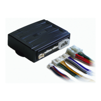
1 – purple
- Signal lights output. It switches voltage in red/white wire CN1.
2 – purple
- Signal lights output. It switches voltage in red/white wire CN1.
3 – white
- siren output. When activated provides +12V.
4 – grey
- common wire for supply of the trunk opening mechanism. Can be connected to the +12V wire or
earth.
5 – grey/white
- relay output for trunk opening mechanism (if supplied with a servo or an electromagnet) can be
used to open the trunk. It switches voltage in the grey CN2.
On this connector the complete relay outputs for control of central locking are located.
1 – yellow/black
- door unlocking relay output (NC)
2 – yellow
- common wire (COM) of unlocking relay
3 – yellow/white
- switch wire (NO) of door unlock relay