1 – blue
- wire grounded when alarm on. It controls
starter-blocking relay and can also be used for
activation of additional modules (interface of el.
windows). Rating capacity 250mA. Second relay
wire of starter-blocking is connected to ignition.
(via the green wire).
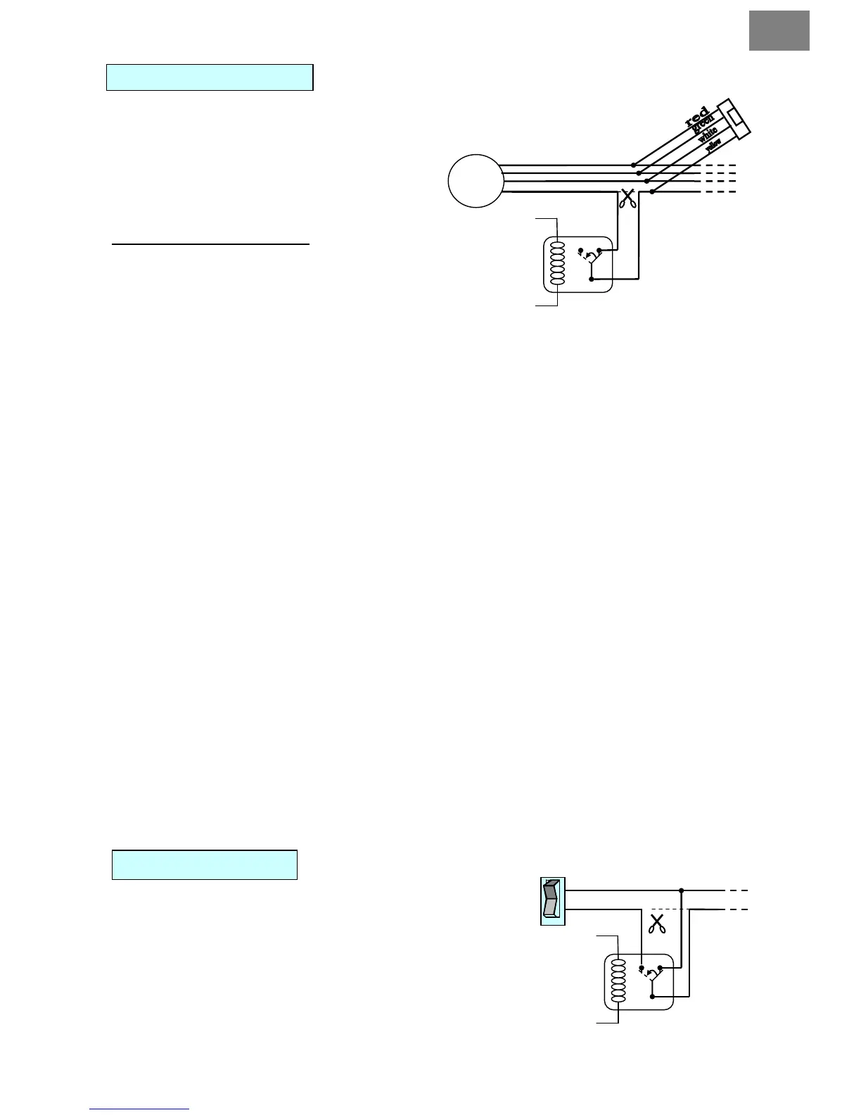
Starter-blocking connection:
When untying the starter wires you must connect
each wire (yellow from relay socket and yellow
from connector CN1) separately! After cutting car
starter lines, you have to connect lines to the relay
outputs used to block the starter.
2 – yellow/black
- alternator or engine rpm scanning.
Alternator scanning – connect to alternator wire. There should appear voltage of at least 5V when
ignition on and engine off, and voltage between 7-14V immediately after the engine is started.
engine rpm scanning – connect to the point where impulses are in proportion to the revs when
engine is running (e.g. crankshaft scanner, gear box scanner – flywheel, distributor, etc.)
3 – red/black
- Negative door switch input ( - )
4 – red
- Positive door switch input (+12V)
5 – white/black
- Negative glow plug input (-). Connects only to diesel engines. If there is signal on this wire when
remotely started – heating is on, system will automatically switch into a diesel mode, and starting
will begin after heating is completed. You may connect the input to e.g.. heating control light.
6 – white
- Positive glow plug input (+).
7 – orange/black
- Negative directional lights input (-). Can by connected to directional lights as feedback control in
sequential control mode.
8 – orange
- Positive directional lights input (+).Can by connected to directional lights as feedback control in
sequential control mode.
9 – grey/black
- Negative trunk switch input (-)
10 – brown/black
- Negative hood switch input (-)
11 –black/white
- Foot brake input reacting on (+)
12 – light blue/black
- Emergency Brake input reacting on (-)
- additional outputs
Additional outputs controlled by the remote control. For settings
see programming menu 2-08, 2-09, 2-10.
When connecting AUX, always check the power supply,
so it will not damage any equipment in the car.
When connecting AUX to electric windows you must
use an additional 12V relay.
For instruments (in the car), which are activated in ACC
or IG1 positions, connect the diode on the alarm wiring
via IG2.