6 (E)
LT20A / LT30 Series
q
r
u
i
tye
w
mm
M A X M I N P — P C P H1 2 3 4
P
RESET
SET
P
MODE COMP
mm
M A X M I N P — P C P L1 2 3 4
P
A+B
BA
A
RESET
B
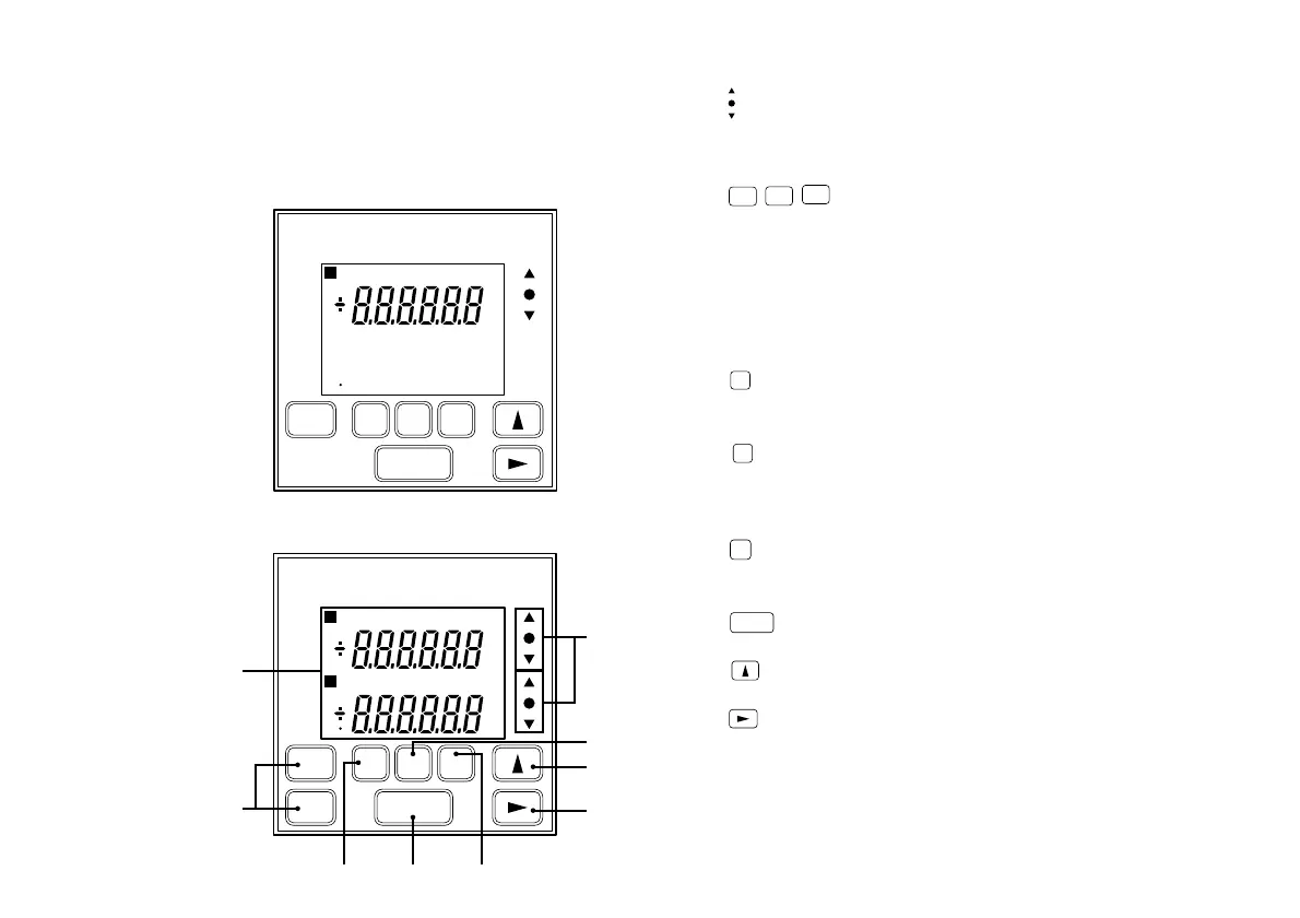
4-1. Front panel
4. Name and function of each part
q : Go/No Go test result indicator
Gives the result of comparing the displayed value to the
comparator’s upper and lower limits. ∆ Over upper limit,
\ between upper and lower limit, ∇ under lower limit.
w
RESET
RESET
A
RESET
B
: Reset key
<For the setting which does not uses the reference
point>
• Resets the displayed value to zero.
• When a value has been preset it returns to this.
<For the setting which uses the reference point>
• When held down for two seconds, the unit enters the
reference point signal input wait status.
e
P
: Preset key
Enters the preset mode. (For the current value,
maximum value, and minimum value.)
r
MODE
: Measuring mode setting key
Key to enter the mode for selecting one of maximum,
minimum, peak-to-peak (maximum–minimum), or
current values.
t
COMP
: Comparator value setting key
Key to enter the mode for setting the comparator upper or
lower limit.
y
SET
: Setting key
Set a mode or a value.
u
: Number selection key
Selects the number for the digit chosen.
i : Digit selection key
• Selects the digit to change when setting numeric
values.
• Normally, when it is held down for 5 seconds, key
lock is established; alternatively, if key lock is already
established, it is released.
Main display
1 CH input model : LT20A-101/101B/101C
LT30-1G/1GB/1GC
2 CH input model : LT20A-201/201B/201C
LT30-2G/2GB/2GC
mm
M A X M I N P — P C P H1 2 3 4
P
RESET
SET
P
MODE COMP
C P L1 2 3 4
 Loading...
