LT20A / LT30 Series
(E) 31
Alarm output
“H” (OFF) is output when the unit enters the alarm state.
This is set to “L” (ON) by pressing the reset key or by the I/O
connector reset input after eliminating the various causes
of the alarm.
Comparator value selection input
The four comparator value pairings set in the counter unit
can be selected.
DRQ display/output hold feature
While the DRQ signal is “L” (ON) the display and output
(BCD, Go/No Go output of I/O connector) of termianls are
stored.
(When the BCD output form is set to
, only the BCD
output data is held on DRQ becoming “H” (OFF).)
However, when the initial settings of pins w and r of the I/O
connector (common) are changed from
which was set at
the time of shipping to
, the hold function for the
display and I/O connector Go/No Go output is enabled only for
pins w and r of the I/O connector (common), and the DRQ
hold is valid only for the BCD output data.
Pin
#5#5
#5#5
#5
H
L
H
L
Pin
#6#6
#6#6
#6
H
H
L
L
Comparator value
(Upper limit CPH, lower limit CPL)
CPH1, CPL1
CPH2, CPL2
CPH3, CPL3
CPH4, CPL4
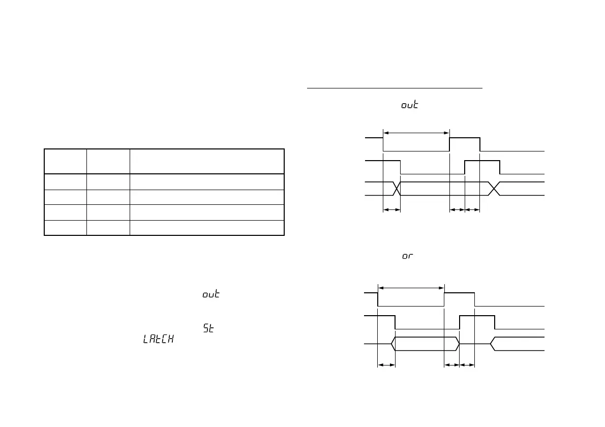
8-2. Signal timing
q-@4 Data, #0 DRQ input, #1 READ output
• When Initial setting (See P15 for factory-set.)
• When Initial setting
DRQ (IN)
READY (OUT)
DATA (OUT)
MAX. 0.2 ms MAX. 0.2 ms MIN. 0.2 ms
MIN. 1 ms
DRQ (IN)
READY (OUT)
DATA (OUT)
MAX. 0.2 ms MAX. 0.2 ms MIN. 0.2 ms
MIN. 1 ms
 Loading...