LT20A / LT30 Series
(E) 29
8. BCD output (only BCD model)
The current value, maximum value, minimum value, and
peak-to-peak value data is output from the BCD connector.
There are also features for alarm output, comparator value
selection input and measuring mode (current value,
maximum value, mimimum value, peak-to peak value)
selection input. The output is all an open collector
equivalent to the IC “74LS06”. With the 2 channel model,
both channel A and B have the same features.
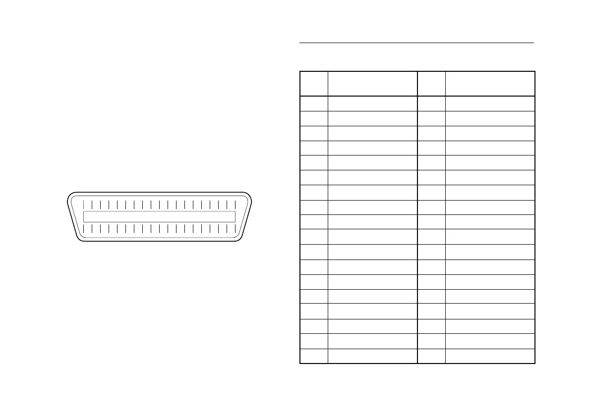
8-1. Connector pin assignment
As seen from the rear of the counter unit.
Connector to be procured
Manufactured by Hirose Electric, Co., LTD
DX10-36S (Counter unit receptacle)
DX40-36P (Plug: accessory)
DX-36-CV (Plug case: accessory)
18 17 16 15 14 13 12 11 10 9 8 7 6 5 4 3 2 1
1936 2021222324252634 33 32 31 30 2935 28 27
Pin
No.
1
2
3
4
5
6
7
8
9
10
11
12
13
14
15
16
17
18
Pin
No.
19
20
21
22
23
24
25
26
27
28
29
30
31
32
33
34
35
36
Signal
1st digit Q1 (A)
Q2 (B)
Q3(C)
Q4 (D)
2nd digit Q1 (A)
Q2 (B)
Q3 (C)
Q4 (D)
3rd digit Q1 (A)
Q2 (B)
Q3 (C)
Q4 (D)
4th digit Q1 (A)
Q2 (B)
Q3 (C)
Q4 (D)
5th digit Q1 (A)
Q2 (B)
Signal
Q3 (C)
Q4 (D)
6th digit Q1(A)
Q2 (B)
Q3 (C)
Q4 (D)
M-VALID
GND
GND
GND
SIGN output
DRQ input
READY output
MOD 0
MOD 1
Alarm output
Comparator value selection A
Comparator value selection B
Signal