LT20A / LT30 Series
(E) 17
factory-set
factory-set
factory-set
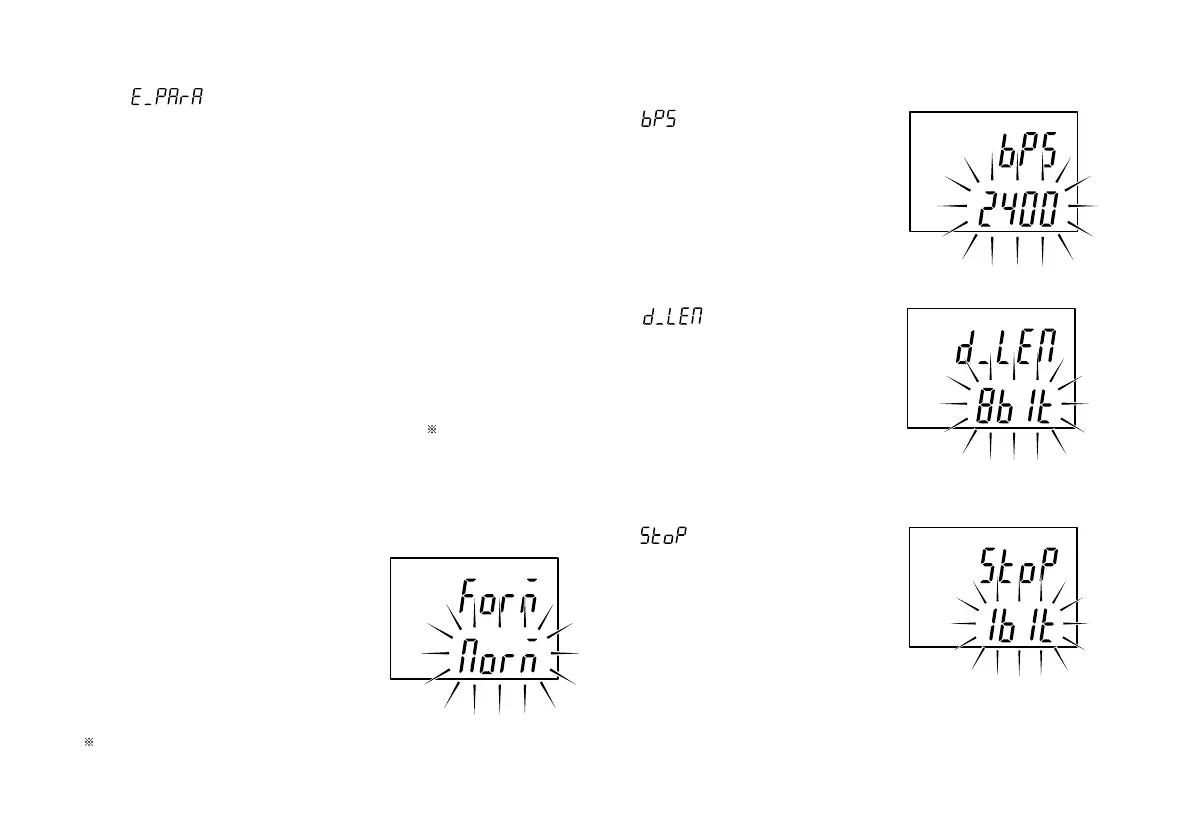
2. Setting the data signalling rate
is displayed and the data
signalling rate can be selected.
2400/9600/19200/38400 bps
3. Setting the data length
is displayed and the
data can be set to 7 or 8 bits.
4. Setting the stop-bit
is displayed and the stop
bit can be set to one or 2 bits.
: Outputting with measuring mode information
and comparator Go/No Go result
1st byte : Channel name (A or B)
2nd byte : Current mode
(N: Current value,
P: Peak-to-peak value,
I : Minimum value,
A: Maximum value)
3rd byte : Unit (M: mm, I: inch)
4th byte : Comparator Go/No Go
result
U : Upper limit over
G : Within range
L : Lower limit under
E : When an alarm has
occurred
5th byte : Sign (“+”
or “–”)
6th to 12th bytes
: Numerical data
(ex.00.0000)
Whether, with the 2 channel model, to output B channel data
following a space or to divide it with the delimiter is selected
by step 9.
: (“+” or space)
factory-set
 Loading...