Quattro DC User Switches C1 Submenu
74
Elevator Speed Regulator (Ereg)
The use of the Elevator Speed Regulator
allows the overall closed loop response
between speed reference and speed to be
ideal for elevator applications. The desirable
features of the Elevator Speed Regulator are:
no overshoot at the end of accel period
no overshoot at the end of decel period
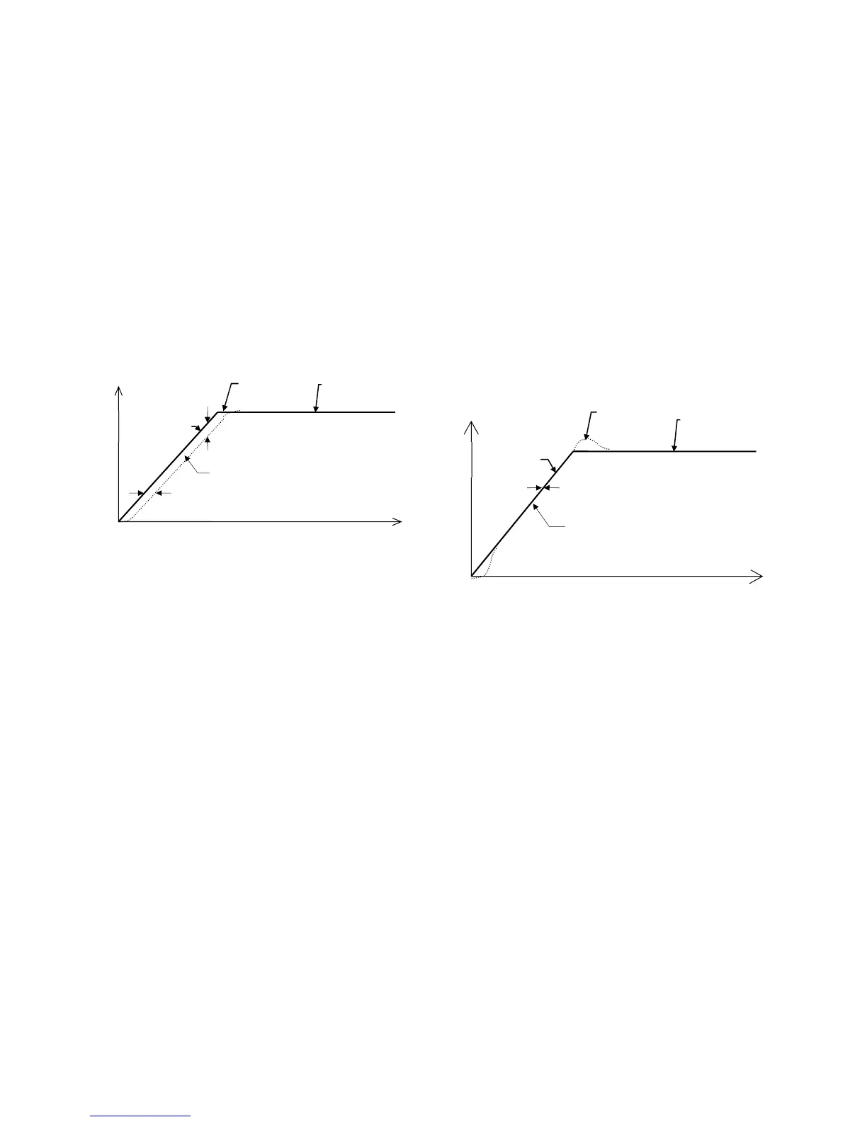
One characteristic of the Elevator Speed
Regulator is that during the accel / decel
period the speed feedback does not match the
speed reference creating a speed error or
tracking delay. As an example, the Elevator
Speed Regulator’s speed response is shown
for a ramped speed reference below.
Ereg Example
The Elevator Speed Regulator is tuned by:
System Inertia parameter (INERTIA(A1)),
which is easy to obtain by using the drive
software to estimate the system inertia.
Response parameter (RESPONSE(A1)),
which is the overall regulator bandwidth in
radians per sec. This parameter defines
the responsiveness of the speed regulator.
The tracking delay shown is defined as
(1/RESPONSE) seconds. The tracking delay
is not effected by the gain reduce multiplier.
The inner loop crossover parameter (INNER
LOOP XOVER(A1)) should not need to be
changed. But if the number is changed, it
must satisfy the following formula:
multiplier
reduce
gain
response
crossover
loop
inner
PI Speed Regulator
When the Proportional plus Integral (PI) speed
regulator is used, the response to a speed
reference is different. As an example, the PI
Speed Regulator’s speed response is shown
below for a ramped speed reference. With the
PI speed regulator, the end of each accel and
decel period, there will be an overshoot. The
amount of overshoot will be a function of the
defined phase margin and response
parameters.
Because of this overshoot, the PI regulator is
not recommended for elevator control by itself.
However, the PI regulator is the proper choice
when a live torque demand signal is available
from the car controller as an always-active
Feed-Forward compensating signal. See
EXTERNAL TORQ SRC (C1).
PI Speed Regulator Example
The PI Speed Regulator is tuned by:
System Inertia parameter (INERTIA(A1)),
which is easy to obtain by using the drive
software to estimate the system inertia.
Response parameter (RESPONSE(A1)),
which is the overall regulator bandwidth in
radians per sec. This parameter defines
the responsiveness of the speed regulator.
Speed Phase Margin parameter (SPD
PHASE MARGIN(A1)) is used only by the
PI Speed Regulator to define the phase
margin of the speed regulator.
speed
feedback
s
eed error
trackin
dela
speed
reference
commanded
s
eed
no
time
speed
feedback
zero trackin
dela
speed
reference
commanded
speed
overshoo
time
s
eed