Flex 8EX / 12EX EU System Instruction Manual
March 2018
Page 31 of 66
4.1.3.3 Inline Pushbutton Configuration (Transmitter Toggle)
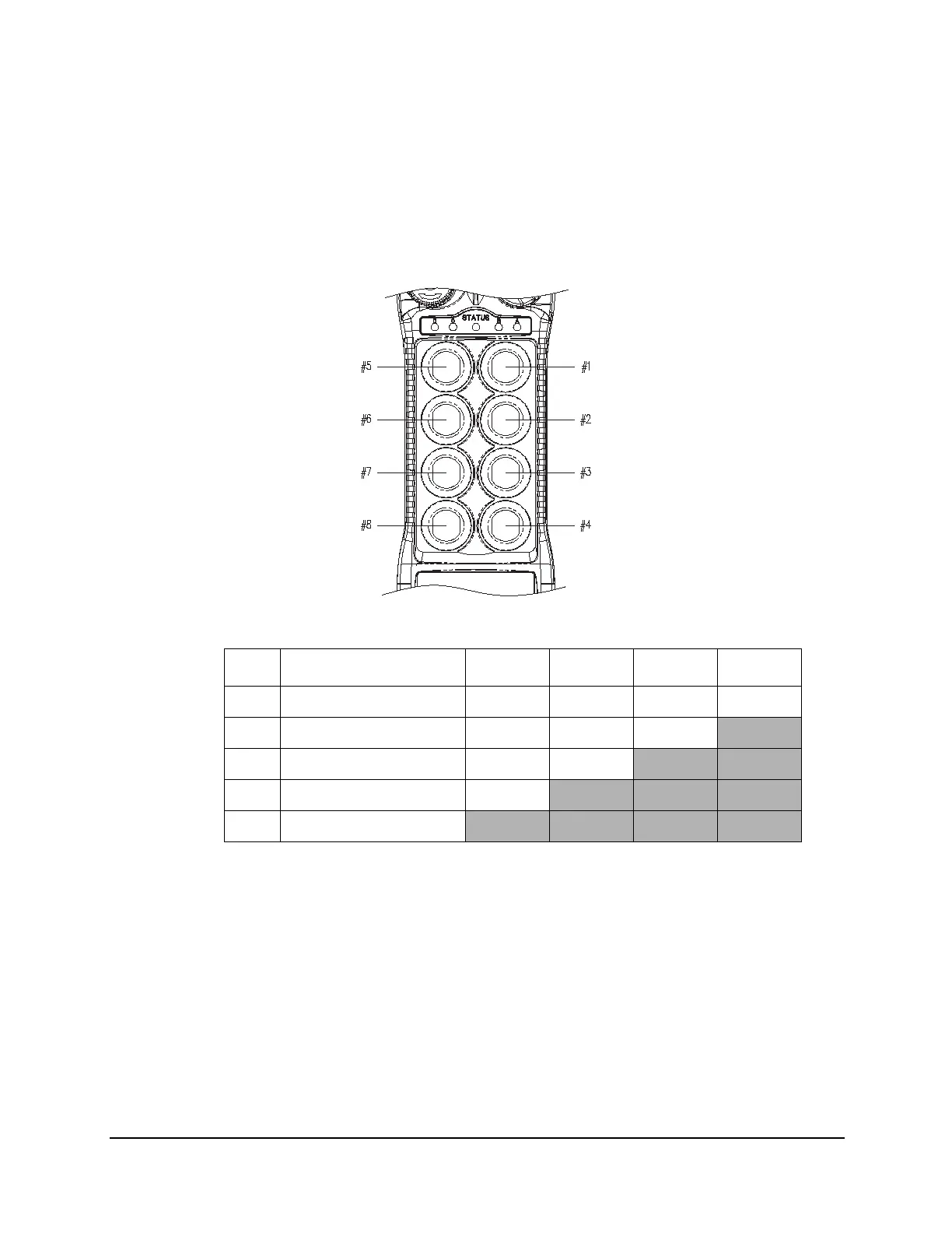
The pushbutton arrangement for inline pushbutton setup starts from top to bottom and
then from the right column to the left column (see Fig. 14 and Fig. 15). To set the inline
pushbutton configuration, see JP4 and JP5 jumper settings in Section 4.2.5 on
page 48. With inline pushbutton configuration, PB1 and PB2 still correspond to output
relay K1 - K4; PB3 and PB4 correspond to relay K5 - K8, etc.
For 8EX:
Fig. 14
NOTE: *PB8 is not available on the A/B transmitters
PB5…PB8 Pushbutton number
Normal Normal momentary contact
LED 1…LED 4 Transmitter toggled with designated LED Display
DIP PB5 PB6 PB7 PB8*
24 00000000 Normal Normal Normal Normal
25 00000101 Normal Normal Normal
LED 4
26 00010100 Normal Normal
LED 3 LED 4
27 00010101 Normal
LED 2 LED 3 LED 4
28 00010110
LED 1 LED 2 LED 3 LED 4