23
Control unit MGCplus
Digital inputs, digital outputs and relay outputs
4 Digital inputs, digital outputs and relay outputs
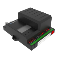
WARNING
Improper wiring and parameterisation of the control unit!
Improper wiring and parameterisation of the control unit can
lead to undesired functions and thus to injuries.
› Only MHTM™ FlowMotion® service experts or skilled techni-
cians or electrical safety experts may wire up and parameter-
ise the control unit.
› The electrical connection of the signal transmitters to the IN1
to IN8 inputs must fit the parameterisation.
ä For parameterisation see ä Page 29, chapter 5.
4.1 Digital inputs
By parameterising the inputs, you assign certain functions to the inputs. Exam-
ple: If you parameterise the "Emergency open" function for input IN1, you
must connect a fire alarm signal to this input. If the signal is interrupted (fire
alarm active), the pedestrian gate is set to emergency mode.
If the function is marked with "|", the input is inverted (Fail Safe), i.e. the func-
tion is activated when the signal is interrupted.
The following functions are assigned to the inputs as default settings.
Clamp Description Function
IN1 Digital Input 1 | Emergency open
IN2 Digital Input 2 Control direction 2
IN3 Digital Input 3 Control direction 1
IN4 Digital Input 4 Control open mode
IN5 Digital Input 5 Random check function
IN6 Digital Input 6 No access
IN7 Digital Input 7 Free D1+D2 OM
IN8 Digital Input 8 RGB illumination off
Table 11: Factory settings "Digital inputs"