Figure 2-16. Our first stando is installed (the rest are waiting in
the wings).
Now we can repeat these steps for the remaining 37-mm stand-
o (see Figure 2-17). When you are all done, plate D should like
Figure 2-18.
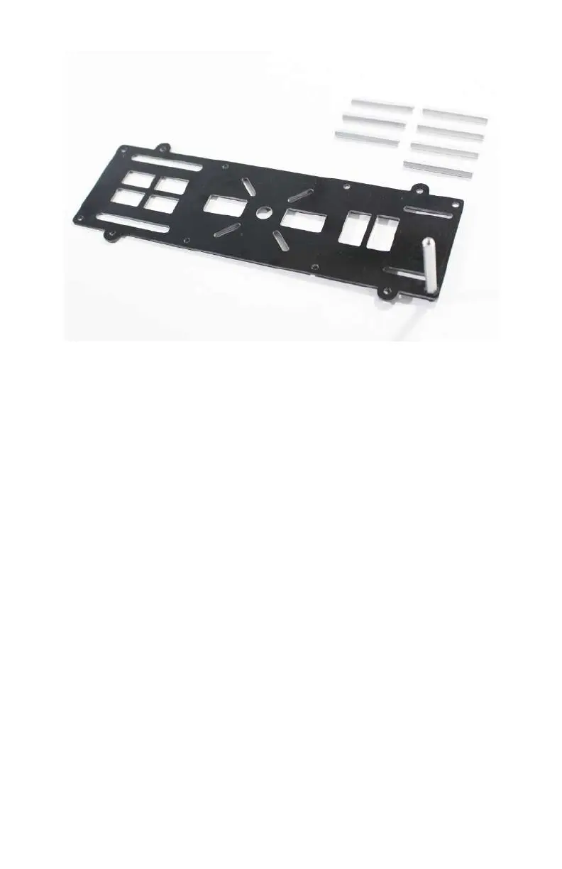
Now that we have our 37-mm standos installed on plate D, we
are ready to attach plate E. If you haven’t done so already, find
that plate and take a close look at it. You will notice two impor-
tant things. First, there are eight identical mounting holes
around the perimeter of the frame (just as in plate D) and sec-
ond, there are two long slots near the edges of the plate on one
end (just as in plate D). Place plate E on top of our assembly and
make sure the two long slots are directly over of the two long
slots on our bottom plate. It should resemble Figure 2-19.
As you may have guessed, we need to thread more 5-mm
mounting screws through the holes in plate E into our standos
(see Figure 2-20). Start by manually placing the screws into the
holes and then tighten them with a 2.5-mm Allen wrench (see
Figure 2-21).
Airframes 33