BOOM RT540E SERVICE MANUAL
4-32 Published 4-20-2015, Control # 502-01
8. Connect all electrical wiring to the boom.
9. Elevate the boom slightly with the lifting device so that
the lift cylinder can be extended approximately 30.48 cm
(12 in) to allow for insertion of the lift cylinder rod end to
the lift cylinder lift box on the bottom of the boom.
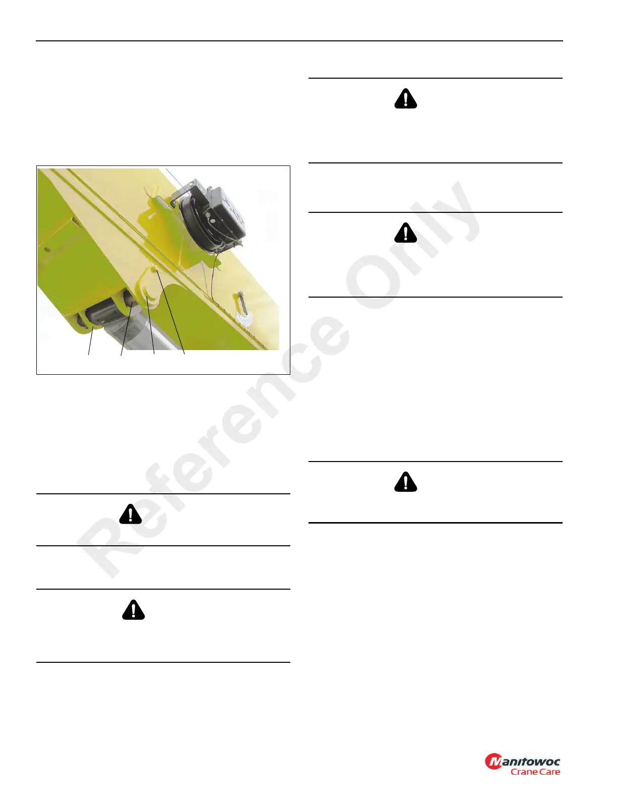
10. Activate the hydraulic system and extend the lift cylinder
rod enough to slide in the lift box (Figure 4-92, 1).
11. Insert the upper lift cylinder shaft (Figure 4-92, 2).
12. Install the upper shaft weldment (Figure 4-92, 3), bolt
(Figure 4-92, 4) and washer to the side of the lift box
(Figure 4-92, 1), securing the upper lift cylinder shaft
(Figure 4-92, 2) on the boom.
13. Remove the boom lifting device.
14. Ensure the Boom is fully retracted.
SWINGAWAY EXTENSION INSTALLATION
NOTE: Tag line used in these procedures is to control the
movement of the boom extension.
1. Crane should be set up on outriggers using normal
setup procedures as found in the Operator Manual.
a. Fully retract boom.
b. Lower boom to horizontal extending over the front of
the crane.
2. Attach a lifting devise to the lifting lugs on the swingaway
extension.
3. Attach a length of rope to the boom extension tip to aid in
swinging the boom extension into place ahead of the
boom nose.
4. Raise the swingaway extension to a safe height to move
to the boom and move the extension into place ahead of
the boom nose.
5. Using the rope attached to the top of the boom
extension, manually align the boom attachment to the
boom extension anchor fittings (Figure 4-93, 2).
6. Move the boom slightly up or down to help align the
boom attachment and boom extension anchor fittings
(Figure 4-93, 2).
7. Insert the right side attachment pins (Figure 4-93, 1)
through the boom attachment and boom extension
anchor fittings (Figure 4-93, 2). Install the retainer clips
in the attachment pins.
DANGER
Wear gloves when handling wire rope.
DANGER
To prevent serious injury or death, always wear personal
protective equipment; i.e., a hard hat, eye protection,
gloves and metatarsal boots.
DANGER
Boom angles are used to control speed at which
extensions swing during erecting and stowage. Improper
boom angles will cause uncontrollable swing speeds of
extension.
DANGER
Before attempting to remove the boom extension; read
and strictly adhere to all danger decals installed on the
boom/boom nose, boom extension, and stowage
brackets.
DANGER
When removing the boom extension, ensure that all
personnel and equipment are kept clear of the swing path.
Reference Only
 Loading...


