Published 4-20-2015, Control # 502-01 3-3
RT540E SERVICE MANUAL ELECTRIC SYSTEM
Table 3-2 Superstructure Cab Fuse Box
Table 3-3: Carrier Fuses and Relays
Table 3-4: Carrier Fuses and Relays
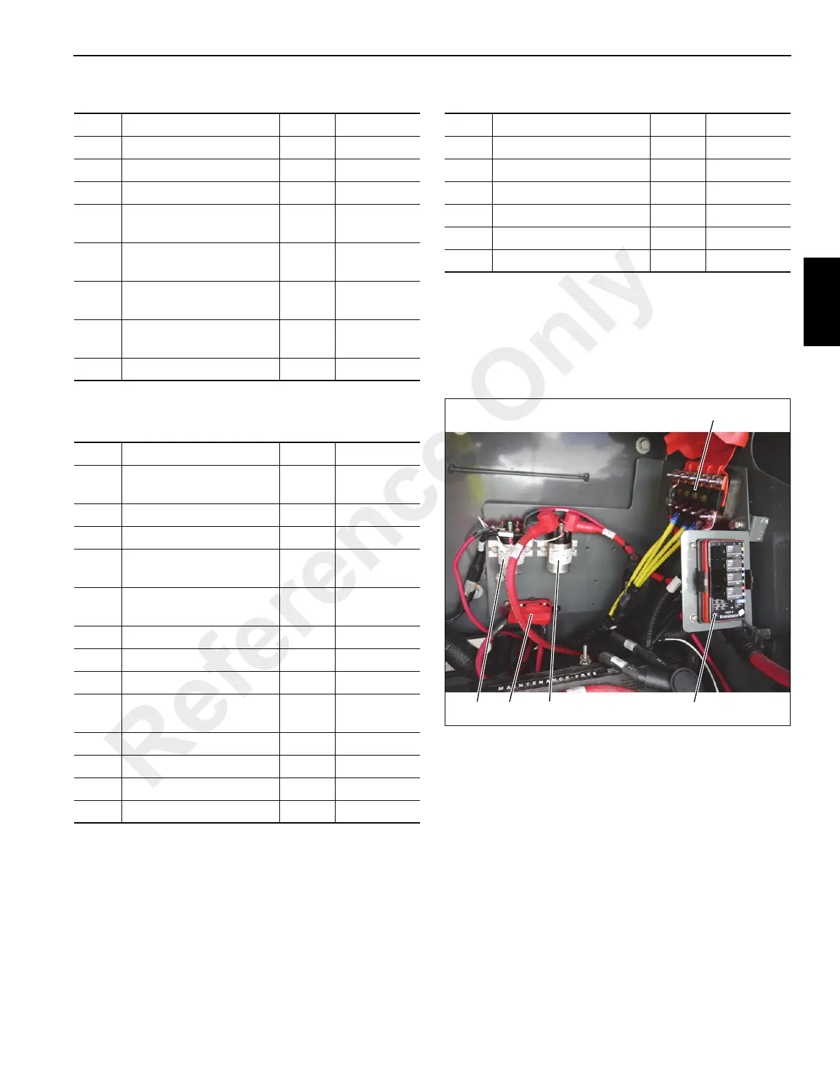
Relays
The relays are located at the back of the battery box
(Figure 3-4): relay K-301 start relay (1) and relay K-302 grid
heater relay (2).
Fuse Protects Amps Location
F1 Keyswitch Ignition Relay 3 (Figure 3-3)
F2 Open (Figure 3-3)
F3 Ignition On Signal 3 (Figure 3-3)
D1
Keyswitch Ignition On
Signal
(Figure 3-3)
D2
Brake Pedal Press
Switch Signal
(Figure 3-3)
D3
Hazard Lights On
Switch Signal
(Figure 3-3)
D4
Marker Lights On Switch
Signal
(Figure 3-3)
D5 Horn On Signal (Figure 3-3)
Fuse Protects Amps Location
F1
Superstructure Module
PCB Power
20 (Figure 3-4)
F2 CraneStar Power 5 (Figure 3-4)
F3 Diagnostic Tool Power 5 (Figure 3-4)
F4
Carrier Module Battery
Power
15 (Figure 3-4)
F5
Carrier Module Battery
Power
15 (Figure 3-4)
F6 Engine ECM Power 30 (Figure 3-4)
F7 Relay Power 10 (Figure 3-4)
F8 Reverse Power 15 (Figure 3-4)
F9
Carrier Module PCB
Power
15 (Figure 3-4)
KC1 Headlight Relay (Figure 3-4)
KC2 Starter Lockout Relay (Figure 3-4)
KC3 Reverse Relay (Figure 3-4)
KC4 Ignition On Relay (Figure 3-4)
Fuse Protects Amps Location
F51 Alternator 100 (Figure 3-4)
F52 Swivel 100 (Figure 3-4)
F53 Swivel 100 (Figure 3-4)
F54 Swivel 100 (Figure 3-4)
F55 Main Power 125 (Figure 3-4)
F56 Grid Heater Power 100 (Figure 3-4)
Reference Only
 Loading...


