Published 4-20-2015, Control # 502-01 4-7
RT540E SERVICE MANUAL BOOM
7. Attach a lifting device to the boom to provide for equal
weight distribution.
8. Disconnect any electrical wiring from the boom.
9. Tag and disconnect the hydraulic lines to the telescope
cylinder. Hard cap or plug the lines and openings.
10. Remove the bolt (Figure 4-5, 1) and washer securing the
upper lift cylinder shaft (Figure 4-5, 2) to the side of the
lift box (Figure 4-5, 3) on the boom.
11. Remove the upper lift cylinder shaft (Figure 4-5, 2).
12. Activate the hydraulic system and withdraw the lift
cylinder rod enough to clear the lift box (Figure 4-5, 3).
13. Take up the slack on the boom lifting device.
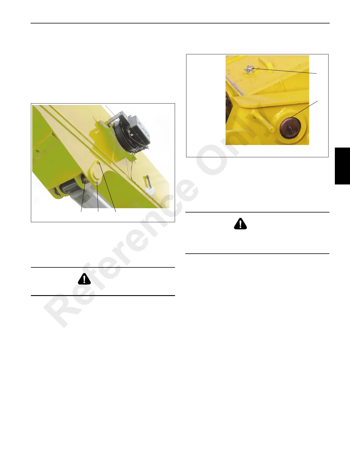
14. Remove the clip pin and retaining pin (Figure 4-6, 1)
securing the boom pivot shaft (Figure 4-6, 2) on the
boom to the superstructure assembly.
15. Remove the grease fittings from the pivot shaft to
prevent damage. Remove the boom pivot shaft.
16. Raise the boom clear of the crane and lower to blocking
or cribbing for service.
Disconnect the Base Section
Do not attempt to work on the boom without experienced
supervision.
.
1. Remove the boom from the crane superstructure in
accordance with “Boom Removal” procedure.
2. Remove the RCL, A2B/Cable from boom nose.
a. Remove cover from junction box.
b. Disconnect “SHD” wire (Figure 4-7, 1) from terminal
1 and “CORE” wire (Figure 4-7, 2) from terminal 2.
c. Disconnect cable connector from side of junction
box.
DANGER
Shut down the crane before proceeding.
DANGER
To prevent serious injury or death, always wear personal
protective equipment; i.e., a hard hat, eye protection,
gloves and metatarsal boots.
Reference Only
 Loading...


