Published 4-20-2015, Control # 502-01 2-17
RT540E SERVICE MANUAL HYDRAULIC SYSTEM
PRESSURE SETTING PROCEDURES
The following procedures should be used to properly check,
adjust and set the hydraulic system pressures.
NOTE: A Digital Pressure Gauge and accessories may be
purchased through Manitowoc Crane Care.
The following equipment is required for checking the
hydraulic pressure settings.
• Pressure Gauge
• Three dial gauge 0-34.5 MPa (0-5000 psi)
• Pressure check diagnostic quick disconnect - Grove P/N
9999101806 and straight adapter fitting 7447040401
• ORFS reducers as required to attach work port hoses to
the gauge.
NOTE: When checking the directional control valve relief
settings, unless otherwise specified, start with the
engine at idle RPM and move the controller to its
fully stroked position. Then slowly accelerate the
engine to the specified RPM. Read gauge and
make adjustments to specified setting.
When checking the outrigger relief valve setting,
start with the engine at idle RPM and activate and
hold the extend switch. Then slowly accelerate the
engine to the specified RPM. Read gauge and
make adjustment as required.
NOTE: GP (Gauge Port) and number corresponds to
gauge ports on the valve and on the hydraulic
schematic.
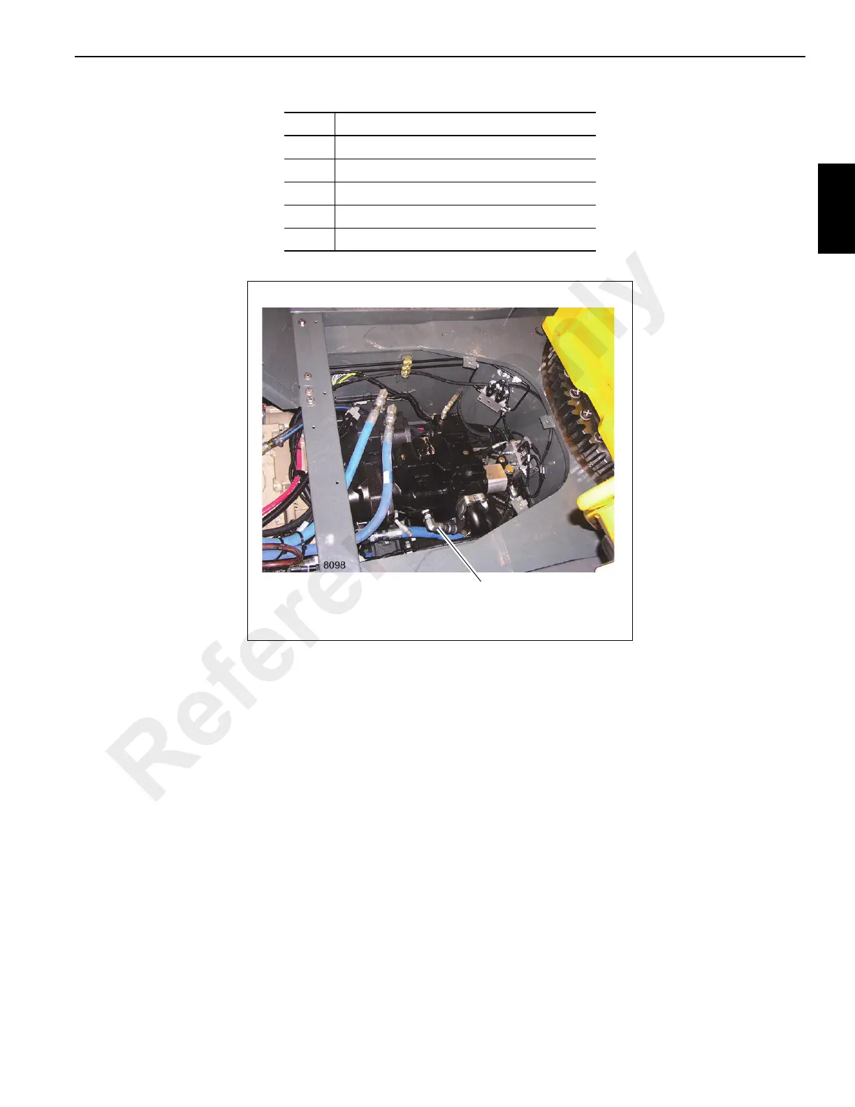
Item Description
1 Pump No. 1 - Piston Pump
2 Pump No. 2 - Gear Pump
3 Pump No. 3 - Gear Pump
4 Transmission
5 Engine
Pump Case Drain
Hose To Reservoir
FIGURE 2-7
Reference Only
 Loading...


