UNDERCARRIAGE RT540E SERVICE MANUAL
8-36 Published 4-20-2015, Control # 502-01
Installation
1. Place the cylinder in the beam.
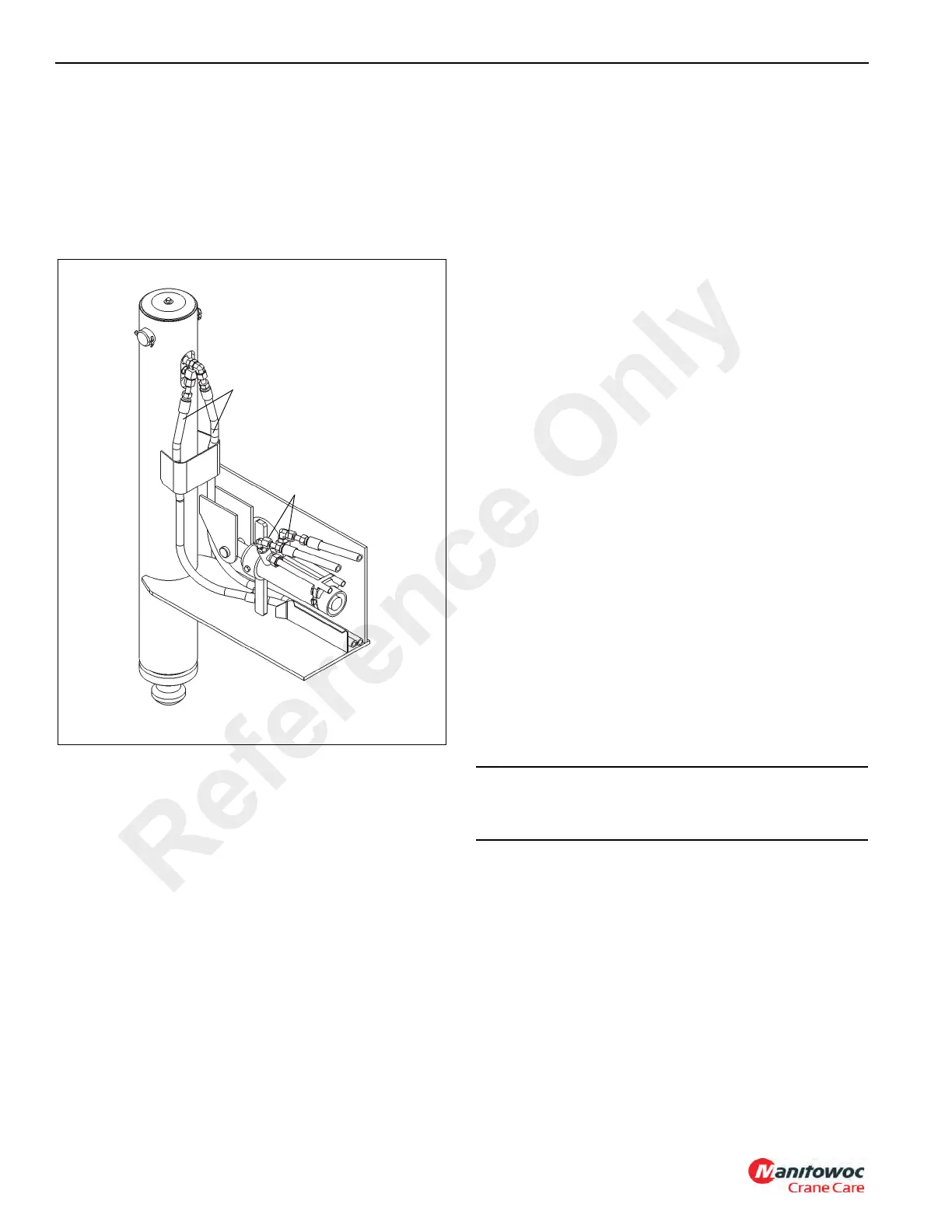
NOTE: Keep hydraulic fittings and hoses close to angles
shown (Figure 8-33) and as low as possible to
prevent rubbing with the beam top plate and side
plate, and for proper tracking during beam
extension and retraction.
2. Position the extension cylinder so the hydraulic ports on
the rod end of the cylinder can be accessed. Connect
the hydraulic hoses to the ports as tagged during
removal.
3. Push the cylinder into the outrigger beam. Align the
cylinder rod with the clevis in the beam. Apply anti-seeze
to the clevis pin and secure in place with the clevis pin
and cotter pin.
4. Install the outrigger beam. Refer to OUTRIGGER BEAM
- INSTALLATION in this section.
Functional Check
1. Activate the hydraulic system; extend and retract the
outrigger.
2. Observe the operation of the outrigger beam.
3. Check the hydraulic connections for any evidence of
leakage.
Jack Cylinder
Description
Four jack cylinders are used on the crane, one at the end of
each outrigger beam. The jack cylinders provide the force for
the outrigger beam’s vertical movement. The cylinder weighs
approximately 64.6 kg (142.4 lb).
Maintenance
NOTE: Refer to CYLINDERS in Section 2 - HYDRAULIC
and PRESSURE SETTINGS for Disassembly and
Assembly of the cylinders.
Removal
1. Extend the outrigger beam slightly for improved access
to the jack cylinder; shut down the engine.
2. Tag and disconnect the hydraulic hoses from the jack
cylinder. Remove the fittings from the ports. Cap or plug
all openings.
3. Remove the nut and washer and remove the cylinder
cap.
4. Place a jack capable of supporting the weight of the jack
cylinder at the base of the cylinder barrel. Jack up the
cylinder just enough to relieve any pressure on the
cylinder retaining pin.
5. Remove the cotter pins securing the cylinder retaining
pin and remove the cylinder retaining pin and cylinder
cap retaining bracket.
6. Jack the jack cylinder up just enough to insert the
retaining pin back into the cylinder. Insert the retaining
pin into the lugs on the cylinder and secure the pin in
place with the cotter pins.
7. Fasten a nylon strap onto the cylinder retaining pin and
use an adequate lifting device to lift the jack cylinder out
of the tube on the beam assembly.
Installation
1. Apply grease (EPMPG) to the ID of the jack cylinder
support tube.
2. If removed, install wear ring in groove in bottom of
support tube and in groove at top on jack cylinder.
3. Place a jack beneath the cylinder tube on the outrigger
beam. Using the same method as described under
REMOVAL, lower the jack cylinder into the cylinder tube
on the outrigger beam until the retaining pin is just above
FIGURE 8-33
Fittings
Hoses
8488
CAUTION
Use a nylon strap to remove the cylinder. This will ensure
the retaining pin is not damaged.
Reference Only
 Loading...


